Torque Converter Tech
- Author: Ed Lee
Using the selective (conical) plastic thrust spacer to adjust clutch-release clearance/stack height
You’ll hear some convincing arguments about how the selective (conical) plastic thrust spacer is used to adjust the stack height on the GM 298mm torque converter. You also will hear some convincing arguments about how this same selective thrust spacer is used to adjust the clutch-release clearance on the GM 298mm converter. The truth is that both statements are correct. The selective (conical) plastic thrust spacer may be used to adjust both the stack height and clutch-release clearance on this converter. What is important is to be aware that changing the adjustment of one also changes the other. As long as you know the proper parameters and parameter limits of both measurements, you can adjust both successfully.
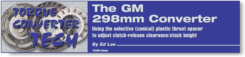
The selective (conical) plastic thrust spacer fills the void between the cover and the turbine hub. Spacers are made in six different thicknesses and numbered 2 through 7 (see Figure 1). They vary in thickness between 14.6 millimeters (0.575 inch) and 16.8 millimeters (0.661 inch). The different thicknesses of the spacers are used to vary the distance between the cover and the turbine hub. The outside diameter of the spacer has an O-ring that makes a hydraulic seal between the spacer and the torque-converter-clutch (TCC) plate. The inside diameter of the spacer has a clearance fit on the smooth front surface of the turbine shaft (input). It is in contact with the O-ring on the turbine shaft and also makes a hydraulic seal.
The front thrust surface of the spacer is in contact with the cover, and the rear thrust surface is in contact with the turbine hub. The turbine shaft, turbine hub, TCC and conical spacer all rotate at the same speed. The conical spacer is not splined or affixed to the other members of the unit, but the drag of the two O-rings and the hydraulic force on the spacer keep it rotating with the other members. The damper assembly of the TCC is splined to the turbine hub, so they rotate at the same speed. The distance between the cover and the turbine hub is governed by which selective thrust spacer has been chosen. Once the thrust spacer is in place, the distance between the two parts remains the same, but the TCC is free to travel between the cover and the turbine hub. The TCC is hydraulically forced forward for TCC apply and hydraulically forced rearward for TCC release.
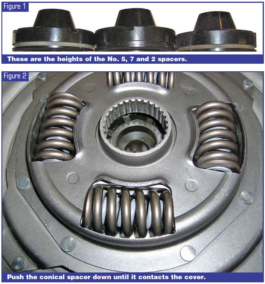
To check the clutch-release clearance, place a selective thrust spacer, preferably with a fresh O-ring, into the TCC plate. Put the clutch plate into the cover. The friction material of the clutch plate should be resting on the mating surface of the cover. Push the selective spacer (see Figure 2) down until it contacts the cover. This is the relative position of the spacer to the clutch plate in TCC apply. Gently remove the plate from the cover and measure the height of the spacer that protrudes above the cover (see Figure 3). In our example, the particular measurement was 0.090 inch. Now take the clutch plate and place it onto the turbine hub. Push it down until the splines of the damper assembly bottom on the turbine hub. This will force the selective spacer up, exposing more of the spacer.
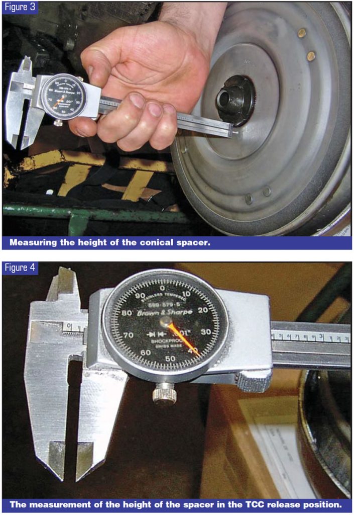
Again, measure the height of the spacer that protrudes above the cover. In our example (see Figure 4), it now measures 0.140 inch. Since this is now the relative position of the spacer to the clutch plate in the TCC release position, subtracting measurement 1 from measurement 2 gives the clutch-release clearance. In this instance it is 0.050 inch. Since 0.030-0.060 inch is the desirable range for clutch-release clearance, this converter will be fine as long as the average overall height falls within the 5.855-inch minimum and the 5.905-inch maximum measurements. If you need less clearance, you can replace the spacer with a thinner one, and if you need more clearance you can use a thicker spacer. Fortunately, when the mating parts of a converter are machined for trueness, both the stack height and the release clearance usually become less. For this reason, increasing the selective spacer by a number or two usually will bring both measurements back to proper specifications.
Communicating with Your Transmission Rebuilder
Increasing line pressure to enhance transmission performance is a common practice in the transmission field. Increasing line pressure also has a direct effect on the converter. As line pressure increases, PR balance becomes upset. This may result in reducing or blocking converter charge oil and lube. As converter charge oil and cooler flow decrease, problems with engagements and overheating can arise. Since converter charge oil becomes the transmission’s lube oil when it leaves the converter, this is not a good thing for the converter or the transmission.
The transmission rebuilder seldom sees the inside of the torque converter. He may not be aware of the damage he might cause by making modifications. On the other hand, when the converter rebuilder sees excessive wear between the selective spacer and the cover (obviously caused by too much converter pressure), he is not helping himself or the transmission rebuilder by not saying anything. This is where better communication is needed.

Ed Lee is a Sonnax technical specialist with a focus on issues of interest to torque-converter builders. ©2005 Sonnax


