TASC Force Tips
- Author: Brian Wing
- Subject Matter: 4L60/E
- Issue: Burnt 3-4 clutches
Attacking 4L60/E burnt 3-4 clutches with confidence
Burnt 3-4 clutch packs are notoriously common in the GM 4L60/E family of transmissions. Tech hotlines and internet bulletin boards are often jammed-up with people pleading for help with this 3-4 roasting. Some technicians get frustrated and throw multiple Hail Mary replacement parts at the transmission when facing this issue. But it doesn’t have to be an exercise in frustration; burnt 3-4 clutches can be transformed from a dreaded problem into a routine moneymaker.
Since the cause of 3-4 burnup can be due to a single failed component or a combination of leaks, the repair that worked last time won’t necessarily work this time — or the next. Compounding the difficulty of diagnosing the original burnup is the fact that it is easy to induce new causes for failure during repair/rebuild. Cracking a pump cover during stator shaft installation or compromising an input shaft seal are common, self-inflicted wounds that lead to smoked clutches. We see the 3-4 burnup issue frequently, but finding the root cause can often be elusive.
All it takes to successfully stare down 3-4 slip and burn — and the anxiety that comes with it — is a good map and a plan to follow. With an understanding of the circuits and components involved, a solid inspection and testing routine that covers all the bases can be adopted. Relying on this routine each time you encounter burnt 3-4 clutches will give you the peace of mind that comes from knowing you addressed all the problem areas and a comeback is not likely.
The long road home
Low line pressure and/or leaks of 3rd gear oil are the root cause of most 3-4 slipping. The 3-4 hydraulic circuit is quite long; it is interconnected to D4, Forward clutch, 2nd, 2nd clutch and 3rd accumulator circuits. Since any pressure change in one part of the circuit affects the rest of the circuit, even small leaks at a few junctions along the way can add up to a big enough pressure loss to allow slipping.
Even if the 3-4 circuit is working perfectly, low or unstable line pressure (and AFL pressure, which affects line pressure) can cause slipping and burning. Like 3-4 clutch oil, AFL and line pressure circuits have common leak points. Any time a burnt clutch pack is found, all three circuits must be inspected methodically to discover and eliminate all the leaks — big and small. The presence of an obvious leak, such as a cracked apply piston, should not stop you from investigating further.
There is a raft of common leak points to inspect; following a path that addresses them all is our goal. Remember: While checking these areas for leaks, we must also be sensitive to various mechanical and electrical considerations as well. Use the following checklist as a convenient guide for hunting down and eliminating 3-4 clutch problems.

Start at the point of failure:
Input drum & shaft
- Air check loaded drum: Ensure 3-4 and forward clutches apply without leakage.
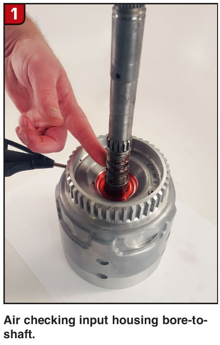
- Air check input housing bore-to-shaft: With an empty and hot housing (straight out of the parts washer), pour oil on housing around spline area. Insert long Vacula®-style blow gun with tip removed into the 3-4 feed port inside the housing, then block feed hole at input shaft sealing rings. Apply pressure and look for bubbles (Figure 1).
If leaks are found between shaft and housing, remove the shaft and inspect for galling/scratches in housing shaft bore (Figure 2).
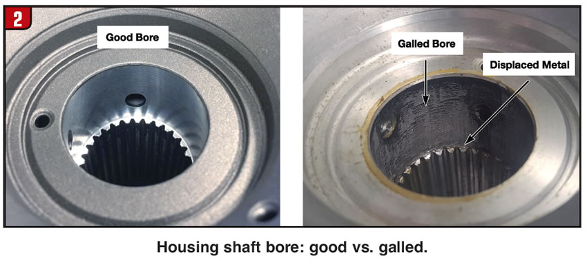
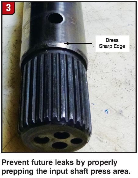
If the bore is galled, a new input housing is required. Galling here happens due to a sharp leading edge on the input shaft press area. Dress this sharp shaft edge and always apply Loctite® above the feed hole in press area when installing an input shaft (Figure 3). Do not allow Loctite to get into feed hole.
- If the input housing checkball leaks, there will of course be a pressure loss. If it gets clogged with debris or muck, clutches can burn in a partial apply due to centrifugal force acting on fluid that can’t exhaust when the clutch is disengaged. The checkball must be able to seal completely and allow free flow when required. Ensure the ball is unobstructed, then vacuum test and reseat the ball if it does not pull 25 in-Hg — anything below 25 inches is an impermissible leak for a checkball. (For information on all references to vacuum testing outside the valve body, see article by Randall Schroeder titled “Seal the Deal,” published August 2017 in Transmission Digest and available in the Sonnax tech resource library at www.sonnax.com.)
- Check for leaking or missing O-ring at input housing to forward clutch housing.
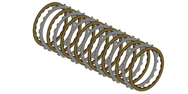
- The weak OE 3-4 backing plate flexes during application, allowing heat to build up unevenly within the clutch pack’s limited space. Burnup is the common result. Stop the flex and you stop a leading cause of 3-4 clutch failure. Thicker, heavy-duty backing plates that completely eliminate clutch pack flex are available in the aftermarket.
- Install new load release springs; never leave them out. The OE piston return spring is very light and needs all the help it can get. Load release springs help keep the apply plate secure from “floating” and assist the return spring in keeping the clutches from dragging and glazing.
- Use available special tools to install and size Teflon® seal rings onto the input shaft. Don’t cut the rings to get them on, and don’t pray that the stator tube will size them down for you.
Stator support shaft
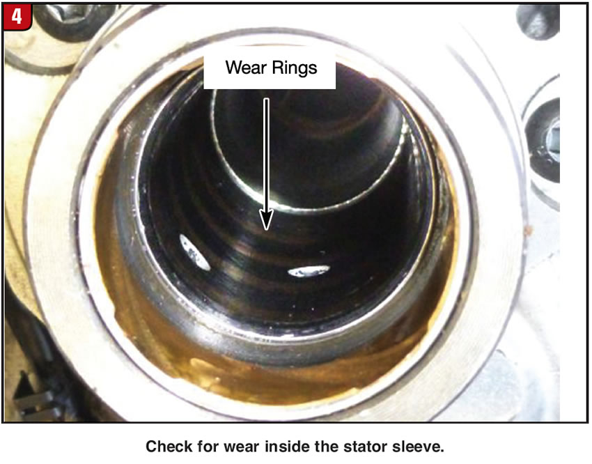
- Inspect for wear inside the stator sleeve where the input shaft seal rings ride (Figure 4). Note: Sometimes when the bushing is removed using a splitter, the seal ring interface area can get damaged.
- Ensure stator sleeve has not rotated and blocked feed holes.
- Replace the stator support bushings. The front and rear stator support bushings are vitally important, but are often overlooked during repairs or rebuilds. These bushings must hold the input shaft steady as it spins so the input shaft sealing rings can contain the oil pressure needed to apply the clutches in the input drum.
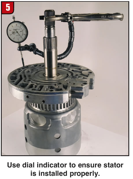
- When pressing the stator shaft into the pump cover, use caution and support the assembly properly to avoid stressing and cracking or warping the pump. To ensure installed stator is perpendicular to pump, place bearing on input housing, then place pump cover onto housing and rotate 360° while observing dial indicator (Figure 5). There is no published spec, but if more than a few thousandths of runout exists, inspect assembly and rework or replace as necessary.
Pump
- Boost valves are notorious for leaking, particularly with high line pressure. Vacuum test and replace where necessary.
- The boost sleeve actually moves in the pump, causing the bore to wear; when replacing boost assembly, install an aftermarket boost sleeve equipped with external O-rings to prevent leakage.
- Vacuum test pressure regulator valve and replace as necessary — this can cause line pressure instability when worn.
- Check for a sticking pump slide. To do this, assemble clean and dry pump halves with just the slide inside. Shake the pump and you should hear the slide moving around inside. A binding slide can often be the cause of otherwise unexplained low line pressure.
- Check for worn pump slide pivot pin and replace as necessary.
- Vacuum or wet air test to ensure pressure relief check ball does not leak.
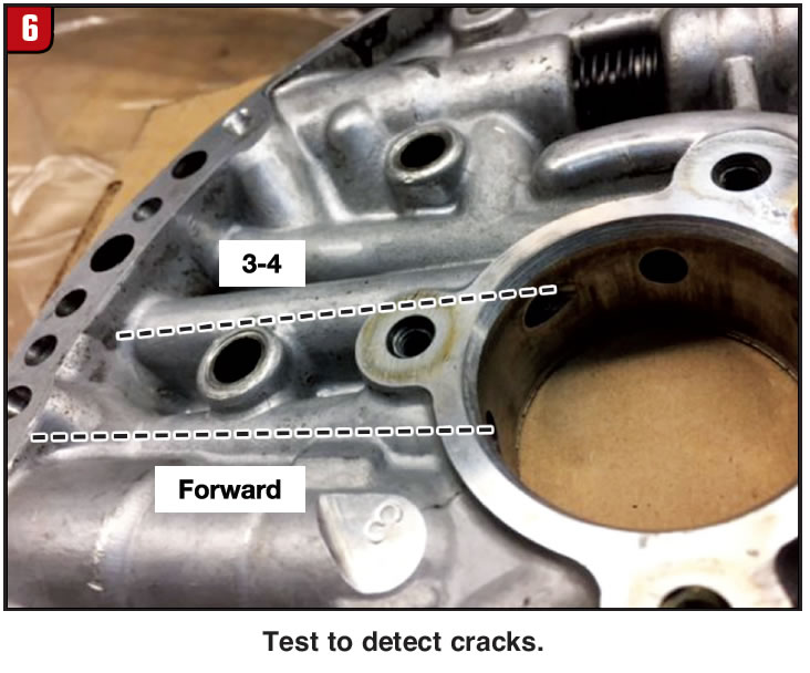
- Vacuum or wet air test 3-4 and forward oil passages in pump, as these areas can develop a hairline crack (Figure 6). Also test with stator installed to ensure there are no leaks between stator and pump at press fit area.
- File or flat-sand both sides of pump to remove dings or high spots that can allow leaks and cross leaks.
Servo
- The servo serves as the 3rd accumulator; always vacuum or wet air test the 3rd accumulator checkball capsule for leakage, as a leaking capsule is a leading cause of 3-4 clutch failure. Test new ones as well, since they are known to leak right out of the box. Reseat checkballs as necessary.
- Some technicians will eliminate the 3rd accumulator checkball and install a cup plug to prevent chronic leakage. No leak, no failure — or is this true? Remember that the ball is not only a seal for containing oil, it is a vent when air is needed to exhaust oil. When a plug is put into place, the vent is choked off, preventing necessary exhausting of the circuit. Replacing the 3rd accumulator ball with a cup plug often results in soft 2-3 shifts and 3-2 flares due to arrested venting. Forget the ill-advised plug; fix the checkball capsule instead.
- Vacuum test 2-4 servos for leakage. Recommend using D-rings instead of Teflon seals.
- Vacuum test piston pin bore to pin.
- Vacuum test servo pin bore to pin.
- Install aftermarket pin that has O-ring at 2nd piston interface.
Accumulators
Since 3rd Gear oil is connected to forward and 2nd clutch circuits, we must eliminate leaks from the forward and 1-2 accumulator circuits. Oil commonly leaks past the pins due to wear created by high cycle rates, which can also wear the piston bore and cause the piston to cock in the accumulator bore. Solutions are available in the aftermarket that both eliminate the pin (and the leaks that go with it) and provide more piston stability.
Stop valve body bleeding
The foundation of a good unit is a tight, leak-free valve body. Controlling leaks improves line pressure and conserves pump volume to be used where needed. It is common to find bore wear that allows pressure drop in critical areas, such as AFL and TCC regulator bores. All valves/bores listed below play a part in applying the 3-4 clutch pack and must be vacuum tested to determine if replacement or reconditioning is necessary. If you find several leak points, you can tool up to fix them yourself or simply purchase a remanufactured valve body.
- AFL valve
- TCC regulator valve
- Isolator valve
- 3-2 downshift valve (abuse plug)
- 2-3 shift valve
- 2-3 shuttle valve
- 3-4 shift valve
- 1-2 shift valve
- Accumulator valve
- Forward abuse valve
- 3-4 relay valve
- 3-2 control valve
In addition to vacuum testing these valves, the following are other common valve body problems to be on the lookout for.
- Never block the TCC regulator or isolator valves. Even without blocking the TCC valve open, its bore is a high-wear area that leaks 3-4 oil via the 2nd clutch circuit. The isolator valve section of the bore commonly leaks boost oil. Blocking open makes everything worse, as this exposes more line pressure and 3-4 oil to exhaust. Instead of blocking, recondition the bore, replace the TCC valve and install an isolator sleeve.
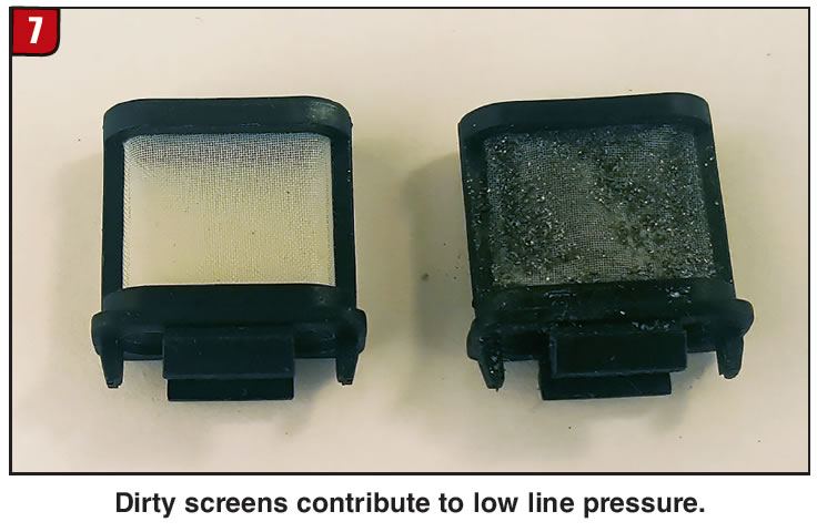
- AFL fluid must pass through a screen filter to arrive at the EPC solenoid. This screen commonly fills with debris, causing a pressure drop in supply to EPC which results in low line pressure (Figure 7). Always replace this screen and the other two AFL screens on the separator plate.
- A sticking 2-3 shift valve is a common failure point.
- The reverse abuse bore plug behind the 3-2 control valve leaks 3rd gear oil and should be replaced.
- Ensure there are no blocked orifices in the separator plate.
- File or flat sand valve body and case.
Electrical
- Address engine codes, as there are a number of codes which can set that will affect transmission operation. For instance, malfunctions with TP, MAP and MAF sensors can all negatively affect line pressure control.
- Test/replace EPC solenoid.
- Ensure there are no impermissible control module voltage drops and that control signals from VCM are correct.
- VB electrical components may be damaged or restricted in a way that won’t be detectable during testing. Pressure switches and solenoid assemblies can hold debris and test well on the bench, but fail in operation.
- If 1996 truck, verify ground wire update per GM bulletin 00-07-30-026.
- Per OEM, add second pan magnet to keep debris away from EPC solenoid.
One road ends, another begins
While the 4L60/E family has reached the end of its production run, there are still millions of units out there that continue to accumulate miles, year after year. Much of the anxiety surrounding 3-4 clutch diagnosis stems from having an incomplete picture of the affected circuits and their components. That apprehension rapidly melts away in the face of a solid plan of attack based on a fuller understanding of those circuits, no matter how long and involved they are. Committing to a comprehensive diagnostic plan based on the road map laid out here — and following it every time you encounter 3-4 burn — is the key to keeping your sanity. Best of all, you’ll be able to confidently collect your fee and send your customers down the road with a long, reliable warranty.