Cast-Iron Powerglide Leaks - Transmission Digest

Cast-Iron Powerglide Leaks

The cast-iron Powerglide® transmission shares one distinction with the motor cars and motorcycles manufactured in the U.K: They all leak. Any transmission-shop owner who is being honest with himself will admit this. Most are not surprised to see the owner of an early-model Chevrolet returning to their shop with a piece of cardboard adorned with a large red spot.

Cast-Iron Powerglide Leaks

TASC Force Tips

Subject: Preventing oil leaks
Unit: Powerglide with cast-iron case
Vehicle Applications: 1949-57 Chevrolets
Essential Reading: Rebuilder, Diagnostician 
Author: Ed Lee

TASC Force Tips

  • Subject: Preventing oil leaks
  • Unit: Powerglide with cast-iron case
  • Vehicle Applications: 1949-57 Chevrolets
  • Essential Reading: Rebuilder, Diagnostician
  • Author: Ed Lee

The cast-iron Powerglide® transmission shares one distinction with the motor cars and motorcycles manufactured in the U.K: They all leak. Any transmission-shop owner who is being honest with himself will admit this. Most are not surprised to see the owner of an early-model Chevrolet returning to their shop with a piece of cardboard adorned with a large red spot.

Over time, many shops have come up with creative solutions for some of the particularly problematic leaks. The OEM cork seal on the TV shaft, for instance, has been replaced by the O-ring that is normally found on the C6 modulator. This upgrade has been very successful. Another example is the use of the metal-clad seal for the aluminum-case Powerglide manual-shaft in place of the cast-iron Powerglide lathe-cut seal. A third example is the cast-iron Powerglide steel speedometer bullet: The OEM speedometer bullet does not have a positive seal, but it can be fitted with the metal-clad seal used in the 350-steel speedo bullets with minimal machine work. This upgrade also has been very successful.

Even with all the creative new sealing alternatives, it is difficult to build a cast-iron Powerglide that is leak free. The owner of a local transmission shop recently mentioned that he was considering no longer rebuilding cast-iron Powerglides. His reason was that all four of the units rebuilt in the past year came back with leaks.

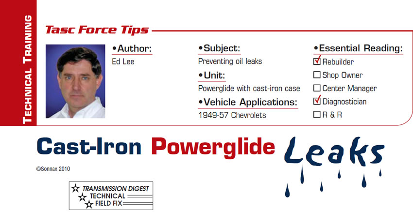
A root-cause analysis was started to find the origin of the leaks. The first thing learned was that, although all cast-iron Powerglides were grouped together, the majority of the reported leaks were in the 1949-57 units. The 1958 and newer units had relatively few reported leaks. A closer look at the different years explained the difference. For the 1958 model year, Chevrolet added a vent to the rear of the main transmission case (Figure 1).

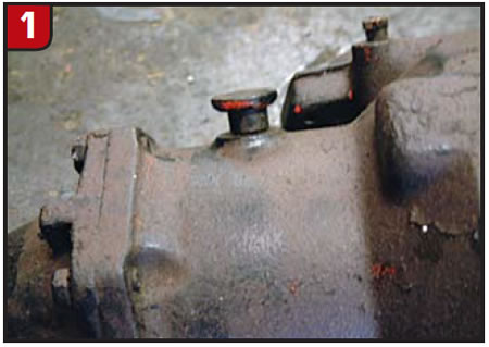
Units from the previous years did not have a vent (Figure 2).

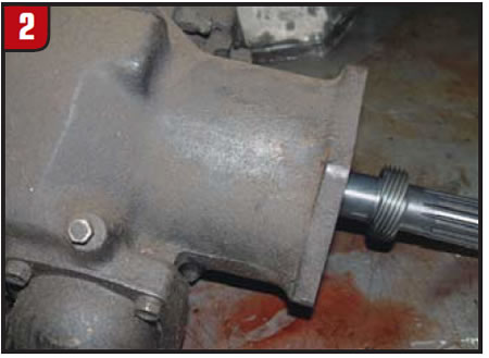
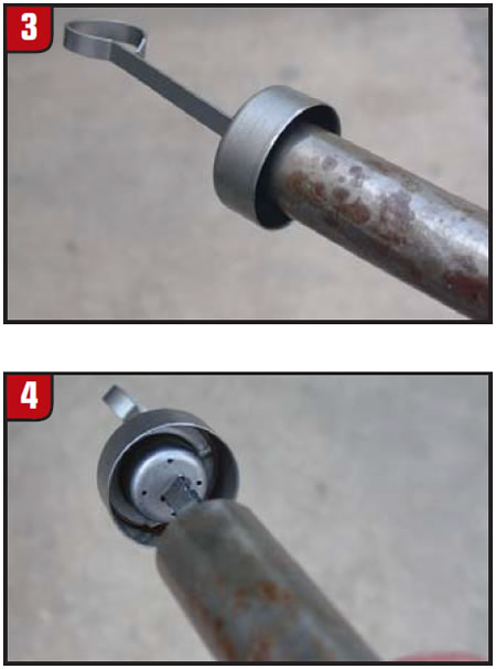
Before 1958, the only vent for the transmission was the opening at the top of the fill tube. The dipstick did not have a positive seal and was designed to allow air to enter and exit the transmission (figures 3 & 4).

The Hydra-matic™ transmission of that day had a similar dipstick, but it entered the transmission at the top of the case and vented the entire main case and extension-housing cavity equally. Since all the cavities of the Hydra-matic were well vented, leaks were not an issue. By comparison, on the cast-iron Powerglide the dipstick tube enters the case at a lower level. This means that – when the fluid is at its proper level – this area is isolated from the rest of the main-case cavity. When all the area inside a transmission case is not vented equally, pockets of pressure are allowed to build up. The vented area of the main transmission case and the extension housing are connected by an orifice in the 11 o’clock position in the rear pump (Figure 5).

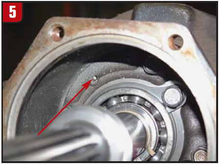
This orifice was restricted by a small pin. Veteran rebuilders of cast-iron Powerglides learned the hard way that leaving the pin out of the orifice in the rear pump would cause the transmission to burp oil out the dipstick tube. Before the vent was added to the main case in 1958, this burping action was the only way that a pressure buildup could be exhausted from the main case. This pressure buildup also explains the numerous stubborn leaks.

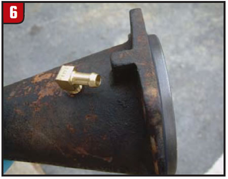
To retrofit a vent to the earlier transmissions, a 90° brass fitting was added to the extension housing (Figure 6). A length of fuel-line hose with a plastic vent from a 350 transmission was attached to the fitting. The end of the hose with the vent was then attached near the top of the dipstick tube.

Unfortunately, this root-cause analysis was started more than 50 years too late for this problem, but I hope it will help with the way we approach future ones.

Ed Lee is a Sonnax Technical Specialist and a member of the Sonnax TASC Force (Technical Automotive Specialties Committee), a group of recognized industry technical specialists, transmission rebuilders and Sonnax Industries Inc. technicians.

©2010 Sonnax

You May Also Like

Sherlock Holmes Approach to an AB60 No-Move Situation

The effectiveness in diagnosing automatic transmission malfunctions is an art form. Although there are similarities among the wide varieties of transmissions on the road, each transmission has its own peculiarities. Aside from having mechanical, hydraulic, and electrical hardware systems to contend with, software/programming issues and various vehicle platforms make diagnostics much more difficult.  Using scopes provides

ab60

The effectiveness in diagnosing automatic transmission malfunctions is an art form. Although there are similarities among the wide varieties of transmissions on the road, each transmission has its own peculiarities. Aside from having mechanical, hydraulic, and electrical hardware systems to contend with, software/programming issues and various vehicle platforms make diagnostics much more difficult. 

GM 6T40 Pump Identification Guide

The 6T40 was introduced in 2008 for General Motors front-wheel-drive cars in the Chevrolet Malibu and has gone through several changes throughout its three generations, specifically in the pump area. The 6T40 is closely related to the more lightweight 6T30 and the heavier duty 6T45 and 6T50. Generation one started phasing out during the 2012

Seeing the Forest AND the Trees

They say that the proverbial phrase “I couldn’t see the forest for the trees” means that a person or organization cannot see the big picture because it focuses too much on the details. Related Articles – 4L60E Harsh 1-2 Shift – TASC Force Tips: Diagnosing 8L45 & 8L90 Shift Complaints – TASC Force Tips: Hydraulics

The Manifold Pipeway

The Honda six-speed transmission has been on the bench of many specialty shops for one reason or another (figure 1). But, for those of you who have yet to lay your hands on one, mounted on the upper side of the unit is one of the largest, if not the largest solenoid and pressure switch

8L90 Vacuum Testing

Below are the diagrams for vacuum testing GM 8L90 transmissions. Note: OE valves are shown in rest position and should be tested in rest position unless otherwise indicated. Test locations are pointed to with an arrow. Springs are not shown for visual clarity. A low vacuum reading indicates wear. For specific vacuum test information, refer

Other Posts

Shift of the shaft: Diagnosing Chrysler 48RE manual shaft issues

The TorqueFlite transmission has been around since mid-to-late 1950s. There have been many changes surrounding the manual shaft and rooster comb through the years. This transmission shaft controls the position of the manual valve that directs oil for the gear ranges, but it also is used for a Reverse light control as well as Park/Neutral

Diagnosing Ford 10R60, 10R80 and 10R140 series speed sensor issues

Ford 10-speed 10R series transmissions utilize four two-wire, Hall-effect sensors — TSS, ISSA, ISSB and OSS — for providing speed signals to PCM or TCM. They are supplied nine volts by a PCM or TCM and assist in the control of clutch apply/release timing that is used in determining shift quality, including TCC. Related Articles

Easy TH400, 4L80-E reverse servo setup: Craft your own tool

While not as sensitive as some shifting bands, the Reverse band adjustment on a TH400 or 4L80-E transmission is critical, and failure to get it right has tripped up even the best builders. There is nothing worse than getting the transmission installed, putting it in Reverse and then not going anywhere or having no engine

Understanding lube flow control valves in Toyota/Lexus UA/UB80 transmissions

The Toyota/Lexus UA80 and UB80 transmissions first came out in 2017 in Highlanders and Siennas. The UA80 is used in V6 applications, and the UB80 is paired with four-cylinder versions. They have been called Toyota New Global Architecture type transmissions, and alternately referred to as the “Direct Shift 8AT” eight-speed automatic transmission. This transmission was

Tasc-Tip-December-Figure-1---LFC-Valve-OE-Partial-Circuit-Diagram-1400