
TASC Force Tips
- Author: Gregg Nader
- Subject Matter: Dealing with servos
- Issue: Modern vs. old-school designs
We see fewer servos in later-model transmissions, but we still deal with them when rebuilding older units. For the most part it is business as usual, except for a few performance applications where a deeper understanding of servo operation can make all the difference when trying to make a transmission stand up to higher power.
Typical reverse servos apply and release at idle with the vehicle stopped. For these applications the return spring powers the release of the servo piston.
For this type of servo, release timing is not critical because the vehicle is not moving.
For servos used on a synchronized shift where the band releases while another element (usually a clutch) applies, release-to-apply timing is far more critical. No common servos used on a synchronized shift rely on spring-only powered release. Servos used on synchronized shifts either have a release area that is greater than the apply area, or they exhaust apply fluid. In both instances, the servo is released by hydraulic power and does not rely on the spring.
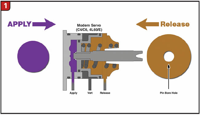
A survey of common transmissions confirms this. Whether it is C4/C6, 727/48RE, 200-4R or 4L60/E, they all have a servo piston-release area that is larger than the apply area, so the release of the servo is hydraulically powered (Figure 1). With their smaller apply area and larger release area, servos in these units all have a “proper” reaction area ratio that ensures the band will fully release. The 5R55W/S OD, AODE OD and 4T60-E 1-2 servos don’t have a larger release area, but they do reduce or exhaust apply pressure when release oil is present, so release is still hydraulically powered.
The Powerglide servo doesn’t work like modern servos. It has spring-powered release, but the spring force can be canceled out by the high oil pressure present in racing transmissions, allowing the band to drag and burn (Figure 2).
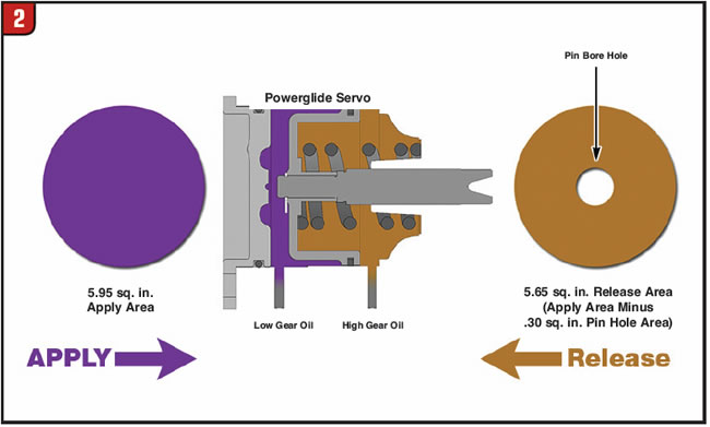
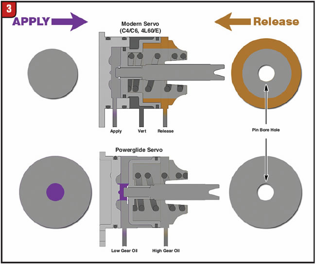
The Powerglide has an outer seal diameter shared by both the apply and release sides, but it’s an older design where apply pressure does not exhaust. On the shift from low to high, there is line pressure on both sides of the servo. This doesn’t mean the forces are equal, however, as the release area EXCLUDES the 0.3 sq. in. area of the pin bore diameter. The result is a larger apply area and smaller release area, an “improper” reaction area ratio also known as the “pin bias effect” (Figure 3).

Not only does the Powerglide servo have zero hydraulic release force, but due to the pin bias effect, there is ALWAYS some apply force for the spring to overcome. The higher the line pressure, the greater the pin bias force and stronger the return spring required. This surprising fact explains many of the band failures in racing Powerglides. With its improper ratio design, the servo return spring force must be carefully calibrated to overcome the pin bias force at a given line pressure. This is possible with a fixed pressure racing valve body, but not practical with variable line pressure.
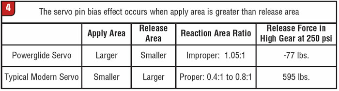
At 250 psi, the pin bias effect built into the Powerglide servo design becomes dramatically apparent (Figure 4). With the typical modern servo example, there are 595 lbs. of force on the servo in the release direction. The band will fully release because no apply force remains. With a Powerglide servo, there are 77 lbs. of force on the servo in the apply direction. The band will not fully release unless the spring is strong enough to correct for the improper reaction area ratio.
How does this Powerglide design idiosyncrasy relate to C4/C6 and 700-R4 and 4L60/E? For the C4/C6, there are old-school modifications published on the internet for removing the smaller-diameter apply seal from the servo piston. This allows the apply oil to react on the full diameter of the servo, and the outer seal is shared by both the apply and release sides. The result is increased servo apply area, but modifications like this have a downside. They introduce the pin bias effect and convert the servo from hydraulically powered release to spring-powered release, resulting in band release concerns.
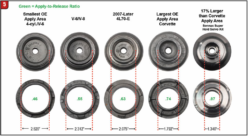
Like the C4/C6, the 700-R4 and 4L60/E servos come in several sizes with proper apply-to-release ratios. These vary from 0.46:1 ratio (old four-cylinder servo) to 0.74:1 ratio for the “Corvette” servo and one OE-style, aftermarket servo with a 0.80 ratio (Figure 5). One modification is to install a different, aftermarket, “slab-style” servo with no cushion spring. It allows apply oil to react on the full diameter of the servo, and the outer seal is shared by both the apply and release sides with an “improper” 1.01:1 ratio. Again, this increases the servo apply area, but like the C4/C6 modification, it converts the servo from hydraulically-powered release to spring-powered release, introducing the pin bias effect and band release concerns.
All common OE servos used on synchronized shifts have hydraulically powered release to ensure clean disengagement, minimal tie-up and avoid band dragging caused by the pin bias effect. When trying to maintain reliability in performance applications, be aware that some old-school modifications fundamentally change the way the servo system works and can introduce new problems that may not be obvious.