Souza Sezz
- Author: Mike Souza
- Subject Matter: Park-by-wire systems
- Issue: Complex electronics & hydraulics
Shedding light on elaborate ‘park-by-wire’ systems on new Mercedes
I understand as transmissions progress in time with the future technologies, things will change and probably become more complicated. Let’s look at what used to be a simple design, the park-pawl components found in many transmissions. We have all heard of or seen the new “park-by-wire” systems found on some of the later transmissions in today’s market. The ZF6HP and ZF8HP have their version of park-by-wire with a release cable that can physically pull the park pawl out of the park position if the vehicle were to lose power. That system was probably the first to be seen in most transmission shops. The earlier park-by-wire system found in the Mercedes 7G-Tronic (722.9) 7-speed rear-wheel-drive automatic transmission does not have a mechanical connection to release the transmission from park if the vehicle loses electrical power.
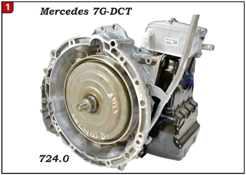
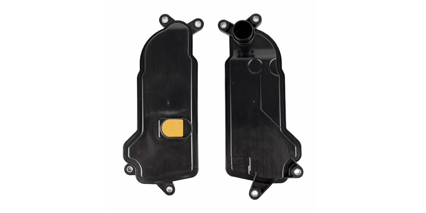
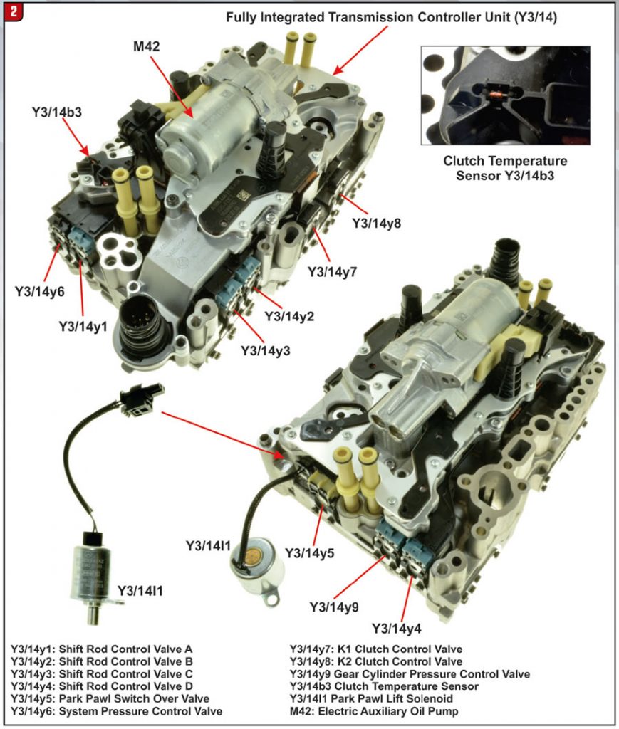
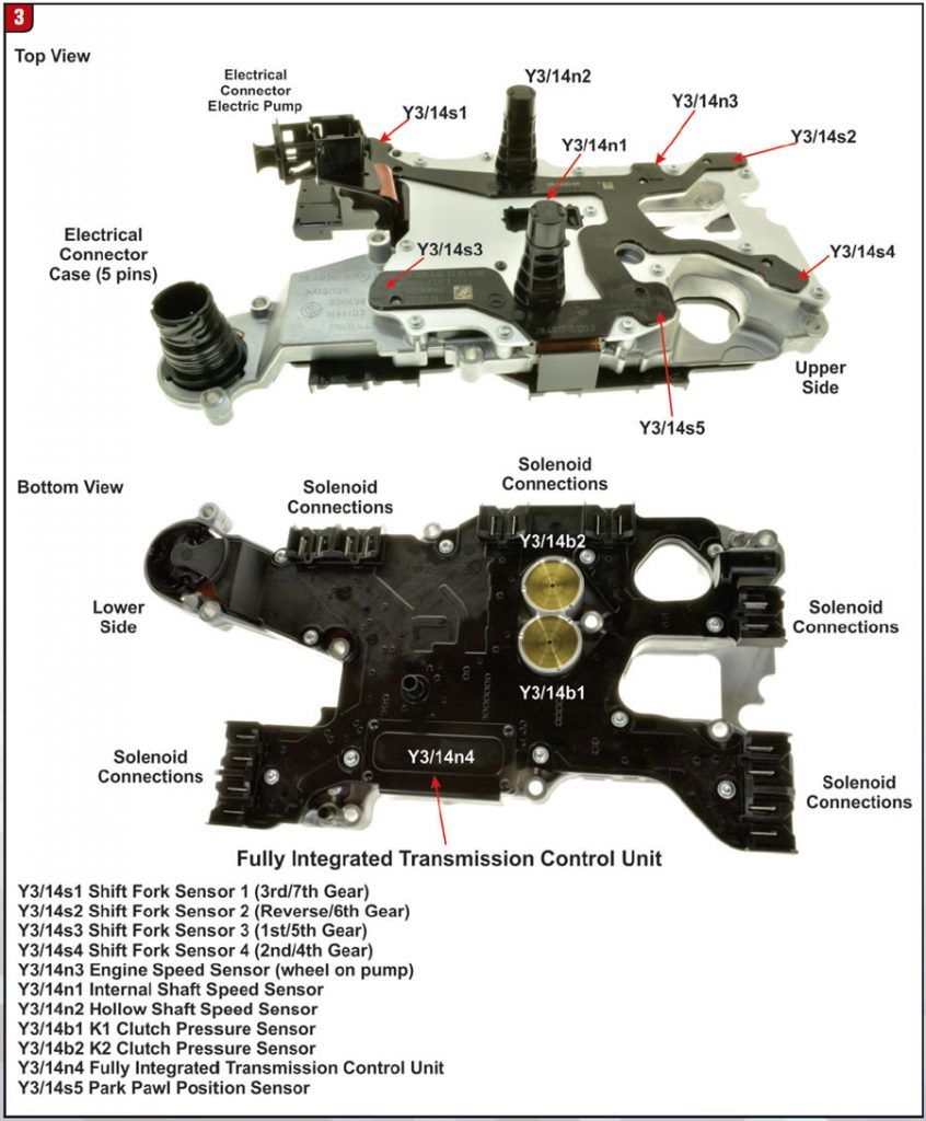
The newer Mercedes 9G-Tronic (725.0) 9-speed rear-wheel-drive automatic transmission and the 7G-DCT (724.0) (Figure 1) 7-speed front-wheel-drive dual-clutch transmission have newer park-by-wire systems that are very similar to each other. They are both equipped with an electrohydraulic control system (VGS) referred to as a fully integrated transmission controller unit (Y3/14). In this article we will discuss the 7G-DCT park-by-wire system. The fully integrated transmission controller unit (Y3/14) consists of (figures 2 and 3):
- Integrated electric auxiliary oil pump (M42) (located on the Y3/14)
- Fully integrated transmission control unit (Y3/14n4)
- Shift and pressure control solenoid valves (located on the Y3/14n4)
- RPM (speed) sensors (part of the Y3/14n4)
- Temperature sensor (part of the Y3/14n4)
- Pressure sensors (part of the Y3/14n4)
- Shift Position Sensors (part of the Y3/14n4)

As you can see there is quite a bit of electronics to go along with hydraulics to control what used to be a simple park-pawl system. The 7G-DCT park-pawl system (park-by-wire) consists of:
- A Direct Select (shift) Lever
- Integrated transmission controller unit (Y3/14)
- Integrated transmission control unit (Y3/14n4)
- Park-pawl switch over valve (P switch valve located valve body)
- Park-pawl lift solenoid (Y3/14l1)
- Park-pawl position sensor (Y3/14s5)
- Parking-lock mechanism
- Park gear (located on output shaft 1)
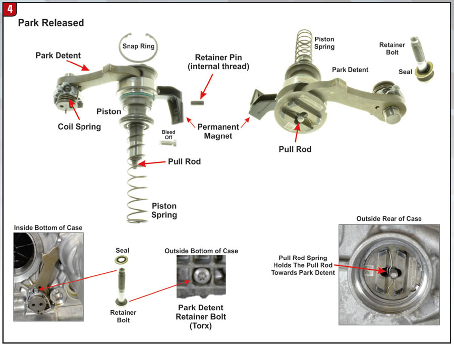
The park-pawl system is located inside the bottom rear section of the case (Figure 4). With the bolt removed from the outside bottom of the case, the park detent section can be removed. The cover is removed from the outside rear of the case to gain access to the park-pawl assembly. The park-pawl lift solenoid (2 retainer bolts) and the permanent magnet (1 retainer bolt) must be removed first, then the threaded retainer pin located under the solenoid (use a bolt to pull the pin out of the case).
Now the park-pawl assembly can be removed through the back of the case. The park pawl is engaged or released electronically and hydraulically. The voltage signal from the integrated transmission control unit (Y3/14n4) is sent to the park-pawl lift solenoid whenever the direct select lever is moved in or out of the “P” (park) position. The pin extends out of the lift solenoid and presses the locking mechanism out of the catch of the piston (Figure 5). The driver’s door must remain closed, if the door is opened while the engine is running the park pawl will automatically re-engage. In the “P” or “Not P” position the park pawl position sensor (Y3/14s5) monitors the permanent magnet attached to the piston (Figure 5) and a signal is sent to the integrated transmission control unit (Y3/14n4).
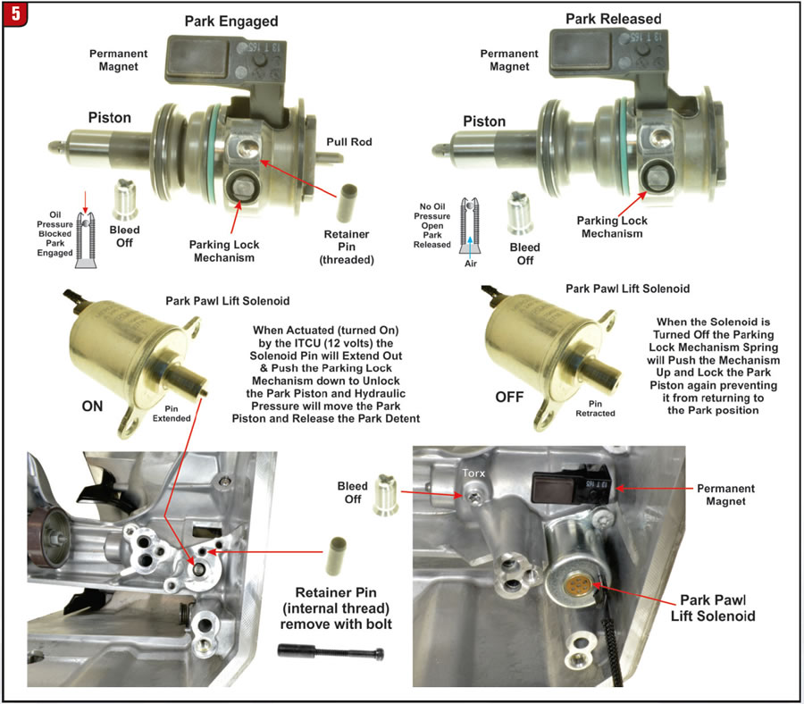
The park detent is held (engaged) into the teeth of the park gear by the contour of the spring-loaded pressure cone (Figure 6). In the “P” position hydraulic pressure holds the piston toward park and a locking mechanism locks the piston in place. the pressure cone spring provides a pre-load on the pressure cone and prevents the vehicle from rolling even if there is no hydraulic pressure.
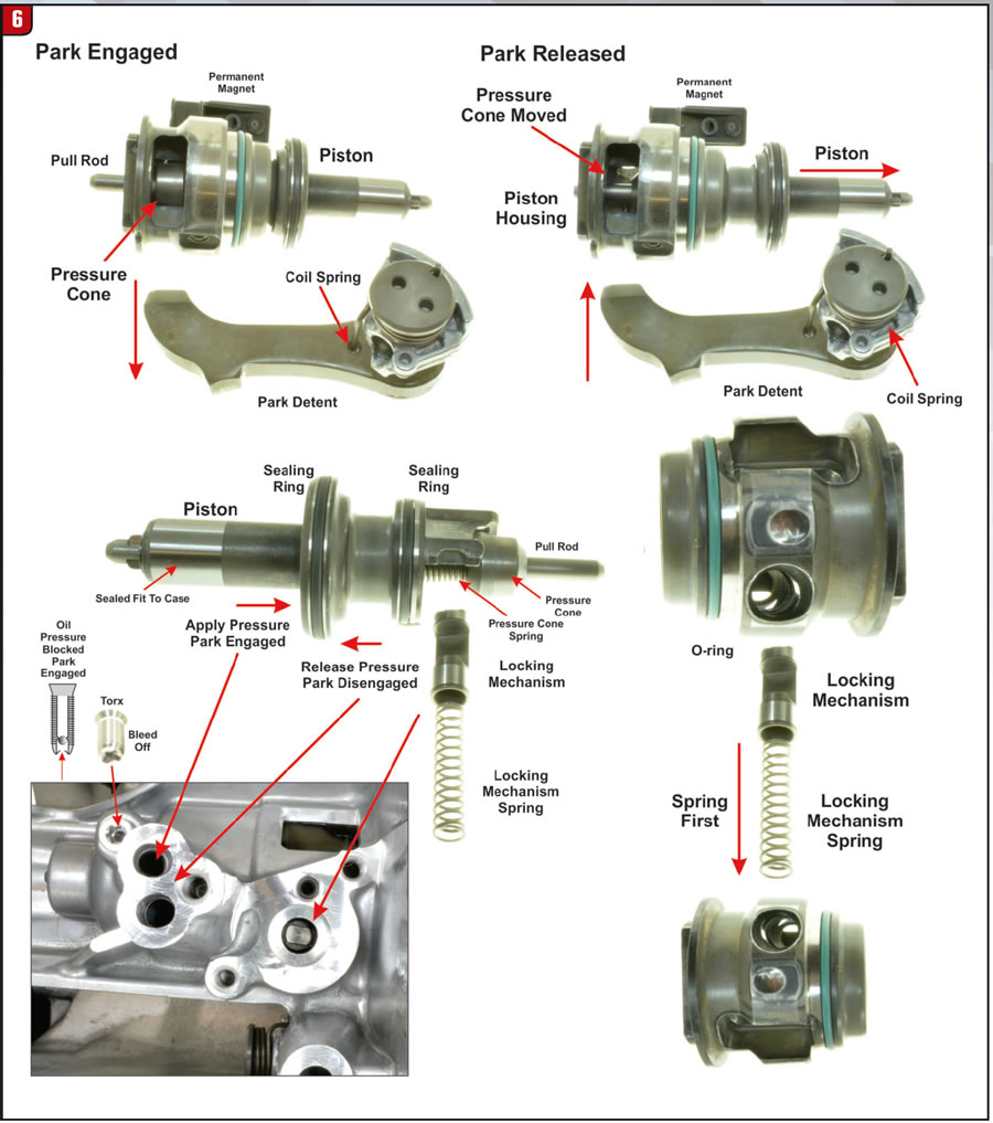
Out of “P” position (“Not P”) the park-pawl lift solenoid is activated (pin extended) to unlock the locking mechanism and the piston is hydraulically pushed toward the piston spring. Then the park-pawl lift solenoid is de-activated (pin retracted) and the piston is locked in place (out of park) by the locking mechanism. When shifting back into “P” (park) position the solenoid will be activated again to release the locking mechanism and hydraulic pressure along with the piston spring will move the piston back to the “P” position. The hydraulic pressure on each side of the piston is provided by the park-pawl switch over valve located in the valve body to move the piston in and out of park. If a loss of power supply or hydraulic pressure occurs while not in the park “P” position, the park-pawl lift solenoid can be energized by an external power source to release the park pawl piston. The park pawl will engage by the piston spring force without hydraulic pressure. It is not possible to release the park pawl without hydraulic pressure.
Now that wasn’t so complicated, was it? NOT! It took me a long time of reading the Mercedes interpretation over and over again, while working with the transmission on hand to finally understand how it works. Even though I thoroughly understand it now, to me, it’s still way too complicated. In my next article I’ll cover the introduction of the GM/Ford 10-speed transmission. Believe it or not, it’s a lot less complicated.