
Technically Speaking
- Author: Wayne Colonna, Technical Editor
- Subject Matter: 7G-DCT
- Issue: An inside look
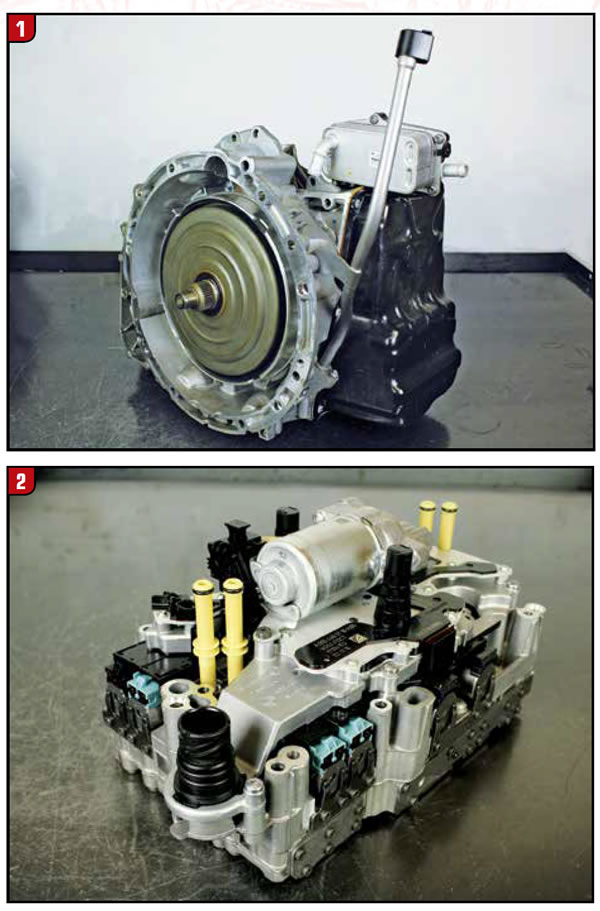
Last month’s article spoke about the susceptibility vehicles have with this transmission to bottom out and break the case. Having one of these on our bench here at ATSG (Figure 1), we will take advantage to look inside this transmission to see what it looks like.
When Mario Aristides brought us this transmission, he already had removed the valve body and its quite an interesting valve body to look at (figures 2 and 3). The fully integrated controller unit (otherwise known as the TCM) is mounted on the valve body. As an entire assembly, Daimler calls it the Electrohydraulic Control System. It consist of 9 solenoids: the K1 clutch control, K2 clutch control, 1st/5th shift control, 2nd/4th shift control, 3rd/7th shift control, 6th/rev shift control and a system pressure control solenoid. The K1 and K2 clutch solenoids measure 5.7 ohms at room temperature. All the others measured 5.4 ohms.
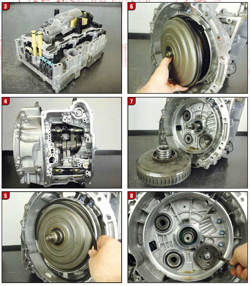
Mounted on top of the assembly is an electric auxiliary oil pump for stop/start technology. Below that aux pump and on top of the valve body is the fully integrated controller unit, which has built into it shift fork position sensors, K1 and K2 pressure sensors as well as a park pawl position sensor.
Looking into the case a solenoid can be seen which is the park pawl lift solenoid (Figure 4). This measured 3.5 ohms at room temperature. Just above it is the magnetic park pawl position sensor. To the left of the park pawl lift solenoid is a magnetic wheel, which serves as an engine speed sensor. Below both the engine speed sensor and the park pawl lift solenoid are two shift fork position sensors. Another set of two can be seen at the very top. Each sensor has two square magnets mounted to a pad on the shift rail. These magnets are susceptible to attracting metal, which will interfere with the signal position of the shift rail. The bottom right sensor (sensor 1) monitors 1st and 5th shift fork position while the bottom left monitors 2nd and 4th gears (sensor 2), top right monitors 3rd and 7th gears (sensor 3) and the top left monitors 6th and reverse (sensor 4) shift fork position.
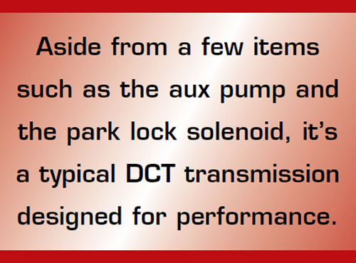
Looking inside the transmission input shaft 1 and 2 can be seen. Each has their own magnetic exciter wheel so the fully integrated controller unit can monitor shaft speed. The sensor ring to the left monitors input shaft 2 (K2 clutch driven), while the sensor ring to the left monitors input shaft 1 (K1 clutch driven).

A snap ring and cover must be removed to gain access to the “wet” dual clutch drum assembly (figures 5, 6 and 7). This double clutch drum assembly is weld closed making the internal components unserviceable. If the clutches have been compromised, an entire clutch drum assembly will need to be purchased. On the backside of the assembly is a drive gear for the pump. Before the two case halves can be separated, the driven gear on the pump must be removed. A punch can be used to prevent the gear from spinning when removing the retaining nut (figures 8 and 9). This pump assembly (which is driven by the Dual Clutch Drum assembly at engine speed) includes the internal engine speed sensor ring that is seen in Figure 4.
When the two case halves are split, input shaft 2 stays with the clutch housing while input shaft 1 stays with the main gear box (Figure 10). A very big word of caution; Be very careful removing the differential from the main gearbox. It has a tendency to bump up against the tapered bearing on the end of output shaft 1. These rollers are held together and onto the inner race with a plastic cage. One little bump and it breaks the plastic cage. When it occurs, its like a miniature explosion ruining your day. Ask how we know about this? Unfortunately we have first-hand experience, because it happened to us (see figures 11 and 12). We are glad to save you from this experience at our expense.
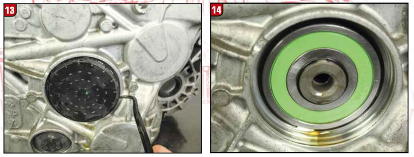
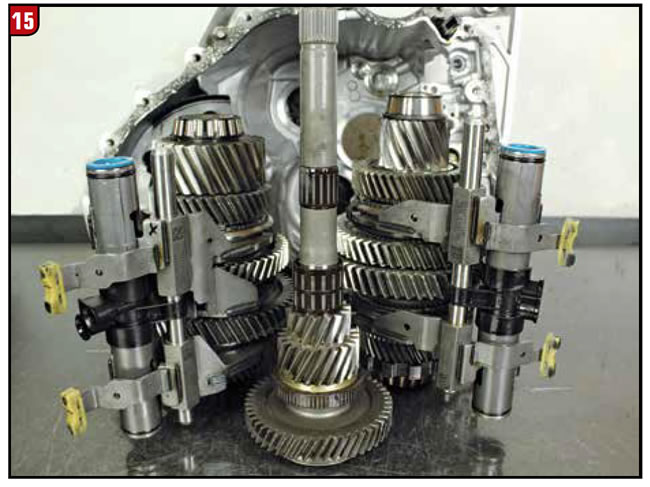
To remove input shaft 1 and output shaft 1 and 2 from the main case, a snap ring must be removed retaining input shaft 1 from the rear case bearing as seen in figures 13 and 14. Once removed, everything comes out of the case (Figure 15).
As with other DCT’s, input shaft 1 is driven by the K1 clutch driving the odd gears. Input shaft 2 is driven by the K2 clutch driving the even gears. The K2 in this DCT also drives reverse. Output shaft 1 in this transmission contains 4th, 2nd, 1st and 5th gears. Output shaft 2 contains 7th and 3rd, rev and 6th gears. Aside from a few items such as the aux pump and the park lock solenoid, it’s a typical DCT transmission designed for performance. Maybe a slight flight in the air is what breaks the case on landing?


