Up to Standards
- Subject: Gear design and operation
- Essential Reading: Rebuilder, Diagnostician
- Author: Mike Weinberg, Rockland Standard Gear, Contributing Editor
Gears date to the beginning of civilization, and the development and advances in gear technology have created the modern world. We as experts in transmissions, transfer cases and differentials work with gears every day, and I thought it would be interesting to examine the theory and design, and some of the geometry involved in gear design.
The tough part is to avoid a long engineering-oriented, highly mathematic discussion that is beyond everybody but graduate engineers. Therefore, we will speak about only what you need to know, and in a depth that we are comfortable with. Even at a minimum some concepts are tricky to understand without some experience with trigonometry, which I failed royally in high school.
Gears are wheels of various sizes that have teeth with which to engage an opposing gear to transmit motion. From there we achieve different ratios and torque ratings to make the rotating torque of an engine usable. Gears are manufactured from many materials, but for automotive use we will dwell on steel alloys.
In mass manufacturing the alloys selected depend on the design, operating speeds, torque load and cost of manufacture. The better and stronger the alloy, the higher the cost to buy and, sometimes, the machining costs. The manufacturer will select the least-expensive product capable of producing the desired results, which is only common sense. Higher torque loads and operating speeds, such as with racing or high-performance vehicles, necessitate the use of higher-performing alloys, as the pricing is acceptable for the user.
After machining, the gears are heat-treated to strengthen the alloy to its correct hardness for the intended use. Alloys typically will grow or shrink during the heat-treat process, and a high level of expertise is needed to create product of uniform specifications. Some companies try to eliminate that by heat-treating a semi-finished gear and them machining the hardened alloy to the final specs. These types of gears are called hard-finished gears, and their cost is usually higher because of the perishable tooling required to cut hardened gears.

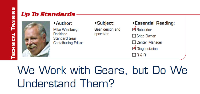
We use external gears – meaning the teeth are on the outside of the gear – which is the common form of transmission gear. The external gear commonly occurs in spur-cut (straight-cut) versions (Figure 1), which are noisy in operation but have no thrust loads.
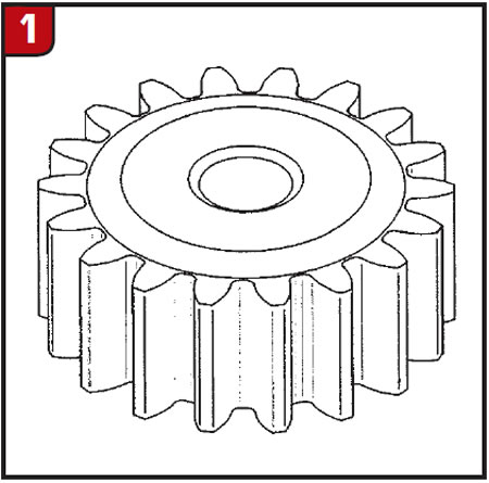
The quietest designs rely on helical gears (Figure 2), which are cut on a curved angle. Helical gears (named from the word helix) operate quietly but produce thrust loads under acceleration and opposite movement (contraction) when the throttle is dropped.
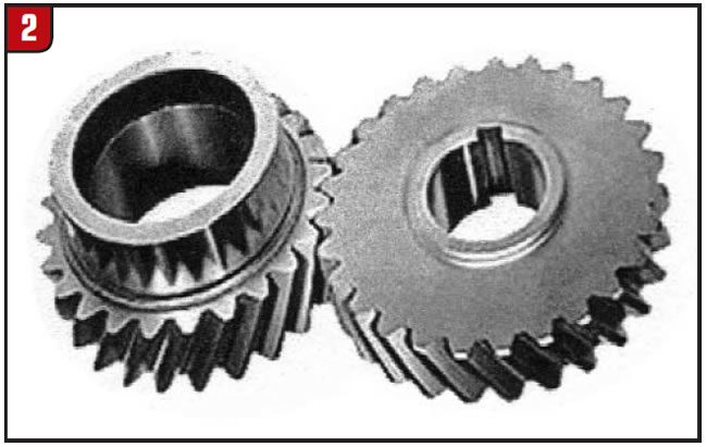
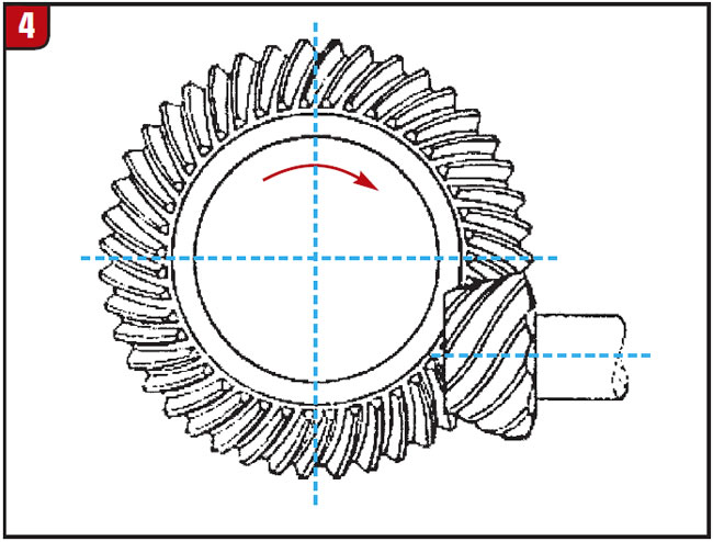
We see internal gears, which have the teeth (straight or helical) on the inside of the gear, in planetary assemblies. There are beveled gears and closely related worm gears, which are used primarily to transfer power 90° from the input rotation. Beveled gears are found in differentials (Figure 3), and when the pinion gear is below the centerline of the ring gear they are called hypoid gears (Figure 4). Worm gears are commonly used to transfer power 90° for speedometer operation.
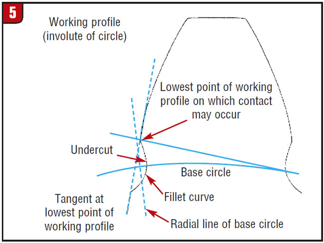
All the gears we’ve just discussed are produced today as involute gears (Figure 5), which describes the profile of the gear tooth. The tooth’s profile is an involute of a circle, which is a spiraling curve traced by an imaginary line unwinding itself from the base circle of the gear. Hard to conceive, but suffice it to say that the profile of an involute gear is rounded.
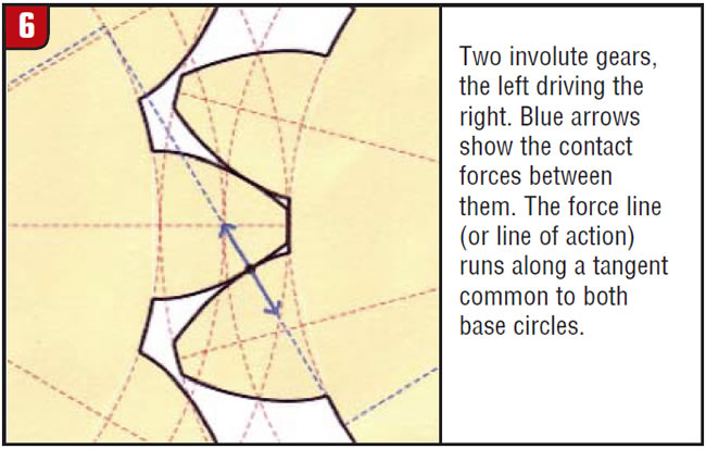
As the pairs of teeth contact each other in mesh, the path they take is called the pressure line, or line of contact. The pressure angle is the acute angle between the line of contact and a normal to the line connecting the gear centers (Figure 6). To work properly the teeth in mesh must have the same pressure angle. Although it is possible to manufacture any degree of pressure angle, the most common is 20° in modern production, with ranges of 14.5° and 25° in some designs. A rule of thumb is that the wider the base of the tooth, the greater the pressure angle, which increases strength and torque capacity. The narrower the pressure angle, the less backlash needed, providing smoother operation and lower heat generation.
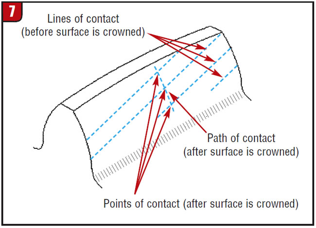
To further strengthen involute-tooth design, the manufacturer may machine back-cuts in the gear at the base of the tooth to create a fillet curve, which reduces the stress risers created by angles between the tooth and the base of the gear. Typically in the gear manufacture the top of the tooth will be crowned to prevent contact with the base of the opposing tooth, and crowning also changes the line of contact on the gear faces (Figure 7).
Helical gears are the most-commonly used gears in modern transmission design. The angle of the teeth is in the form of a helix as they are inclined to the axis of the shafts. Because of the curved angles, the two opposing teeth start to engage and gradually increase as the rotation increases. Helical gears are also called high-speed gears because of their smooth and quiet operation and their ability to take increased torque loads, while the driver can listen to the radio.
Backlash is very sensitive with helical gearing, and you can often find a noise problem by checking the backlash between the opposing speed gears. If one pair is tighter or looser than the other pairs, this may be your problem child. Another issue with noise can come from a twisted tooth or teeth. To solve this problem you need to blue up the gears, reassemble and run the transmission to see what the pattern looks like on the gear faces. If you are lucky you can feel a twisted tooth by rotating the shaft by hand. Helical gears will have a different line of contact from spur gears because of the curved contact angles (Figure 8).
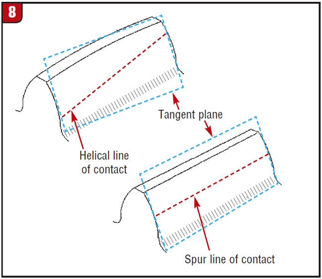
Figure 9 shows some of the design aspects of a typical gear, and the definitions of the terms used in the illustration follow.
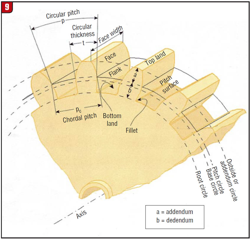
- Addendum: the radial or perpendicular distance between the pitch circle and the top of the teeth.
- Base circle: the length of arc on the circle between the two involute curves forming the profile of the tooth.
- Bottom land: the surface of a gear between the flanks of two adjacent teeth. For external gears it is measured in the root and for internal gears it is measured at the minor tip of the tooth.
- Circular pitch: the distance on the circumference of the pitch circle between corresponding points on adjacent teeth.
- Circular thickness: the thickness of the tooth at the pitch circle.
- Face: the contact point for the opposing gear in mesh.
- Face width: the width of the pitch surface.
- Fillet: the concave portion of the tooth profile where it joins the bottom of the tooth space.
- Pitch circle: the circle through the pitch point having its center at the axis of the gear.
- Root circle: the circle at the root of the tooth having its center at the axis of the gear.
As you can see, this is an introductory idea of the complexity of gear design and geometry. The object is to produce a strong product that will quietly transfer and make usable the engine’s torque. A well-designed gear runs cool and operates smoothly, and at acceptable noise levels. The only thing the factory and the repair facility cannot control is the loose nut behind the steering wheel.