Up to Standards
- Author: Mike Weinberg President, Rockland Standard Gear Inc
- Subject: MP3023
- Issue: Details
Introduced in 2011 in the Jeep Grand Cherokee WK2 series and Dodge Durango vehicles and continuing into 2019, there are a lot of these units on the roads. Magna Powertrain designed and produced the 3023 and 3010 transfer cases. The 3010 series is a single speed active transfer case (no low range) called Quadra-Trac Active on Demand, which is standard on the SRT8 models. The 3023 is a two-speed active transfer case electronically controlled by computer that requires no intervention on the driver’s part. There is a low range mode for rock crawling and other off-road activities and should never be used on dry pavement. All of these transfer cases require that all four tires be of equal tire size and pressure. Mismatched tires will quickly damage the transfer case, set codes, and create a diagnostic nightmare. Before working on any of the vehicles measure your tire sizes and pressures. They must be within 1/4” to operate correctly.
The MP3023 transfer case is capable of the following:
- Active, on demand four-wheel drive without driver input
- Measures individual wheel slip and instantly redirects torque as needed
- Enhanced vehicle stability under any and all conditions as torque transfer is always operational
- Shifts between 4WD auto and low range are accomplished electronically
This transfer case is part of the traction control and electronic stability program (ESP) which measures wheel speed, steering angle, yaw rate, brake pressure, throttle position, transmission gear position and many other factors to keep the vehicle on the desired path through turns.
- There is a neutral mode for flat towing.
- Transfer case operating ranges are 4WD auto, neutral and 4WD low.
- 4WD low produces a 2:72-1 ratio reduction for off road use.

How it operates:
The Drive Train Control Module (DTCM) controls the active wet clutch through the Controller AREA Network (CAN) C bus. Monitoring multiple vehicle sensors through an internal vehicle dynamics model (algorithm) permits the DTCM to compare wheel speeds between the front and rear axles, applying pressure to the clutch pack to increase or decrease torque to the axle with the better traction. Transfer of torque from one wheel to another on an axle happens by Brake Traction Control, which will apply an individual brake to correct conditions to the computer algorithm.
The DTCM controls the wet clutch pack electronically using an electric motor to actuate internal gear train, clutch cam, and low range barrel cam. Alternately splined lined and steel clutch plates are connected to the front and rear driveshafts. Applying a computer-controlled amperage to the clutch pack equalizes the speeds of the front and rear drive shafts. The system is very sophisticated and includes Selec-Terrain, which distinguishes in the algorithm the differences between travel on snow, sand, mud, etc.
Now that we have an understanding of how it is designed to work, we can get to the meat and potatoes and look at some real-world facts that were learned the hard way. There are a lot of these units on the road. The clutch pack is working ALL the time and there are control problems. If you are working on one of these here are some shortcuts to successful repair. Check your tire pressures and size, check for and eliminate all codes and sources of same. Check the t-case fluid; if it is burnt go no further, you will need to rebuild the unit. The lined clutches and steel plates in the clutch pack are very thin and will warp immediately under abuse. Once they are warped, clutch clearance and drag can never be correct and the unit will only be repaired by a rebuild and curing of any external problems that will beat up the clutch pack again.
If the fluid is good and the tire sizes and pressures are correct the most common complaint is binding on turns, and/or a clunk or thud on takeoff. 99% of the time this will indicate a failed position sensor. There are some time-saving issues in replacing the sensor, which we have provided with illustrations that are not covered in the repair manuals. First, line up the sensor arm arrow with the internal line on the inside of the sensor. Line up the shift shaft assembly in the case with the part of the case marked by the red dot. Install the sensor and the bolt holes will not line up. Rotate the installed sensor CLOCKWISE until the bolt holes line up and secure the sensor with the attaching bolts. If you turn the sensor counterclockwise you will be 180 degrees out on the clutch pack with a whole new set of problems. If a new sensor does not cure the problem, the control module will need to be replaced. If you have a shift motor that clicks, it will need replacing.
After all is said and done and all the codes are cleared or fixed, this is our experience on working with many 3023 transfer cases.
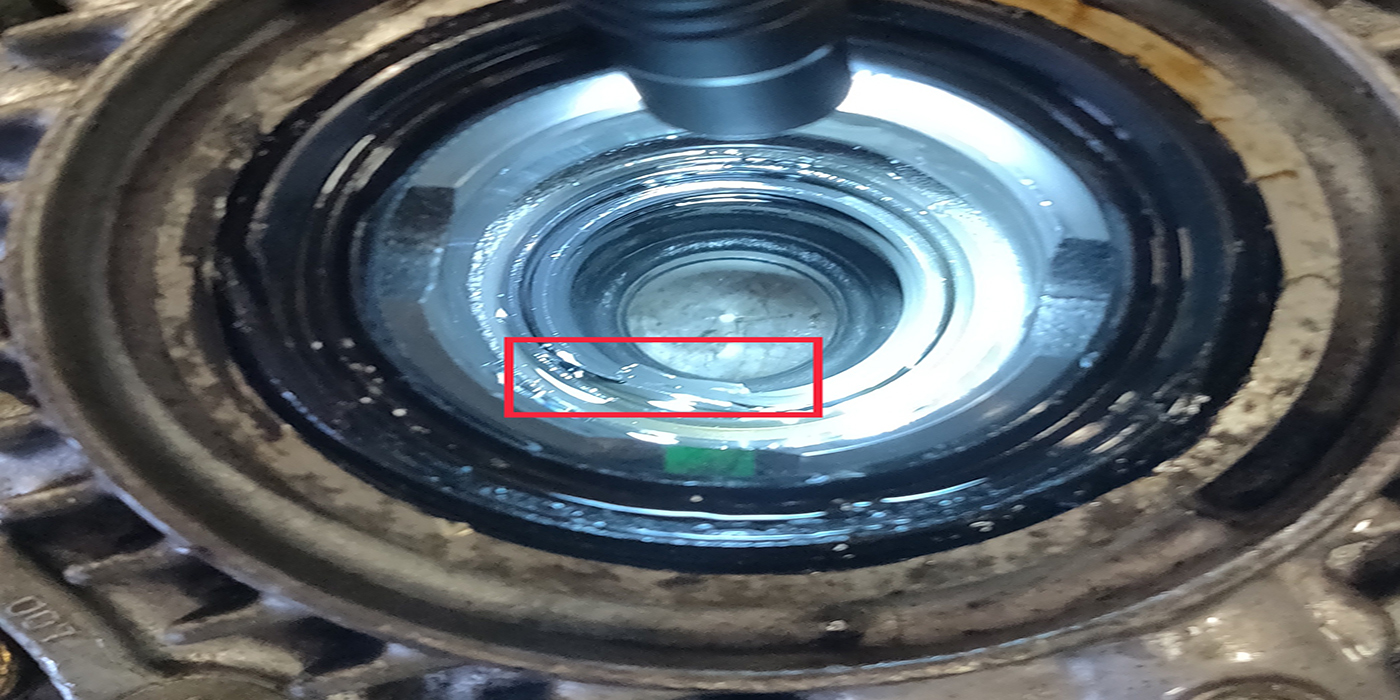
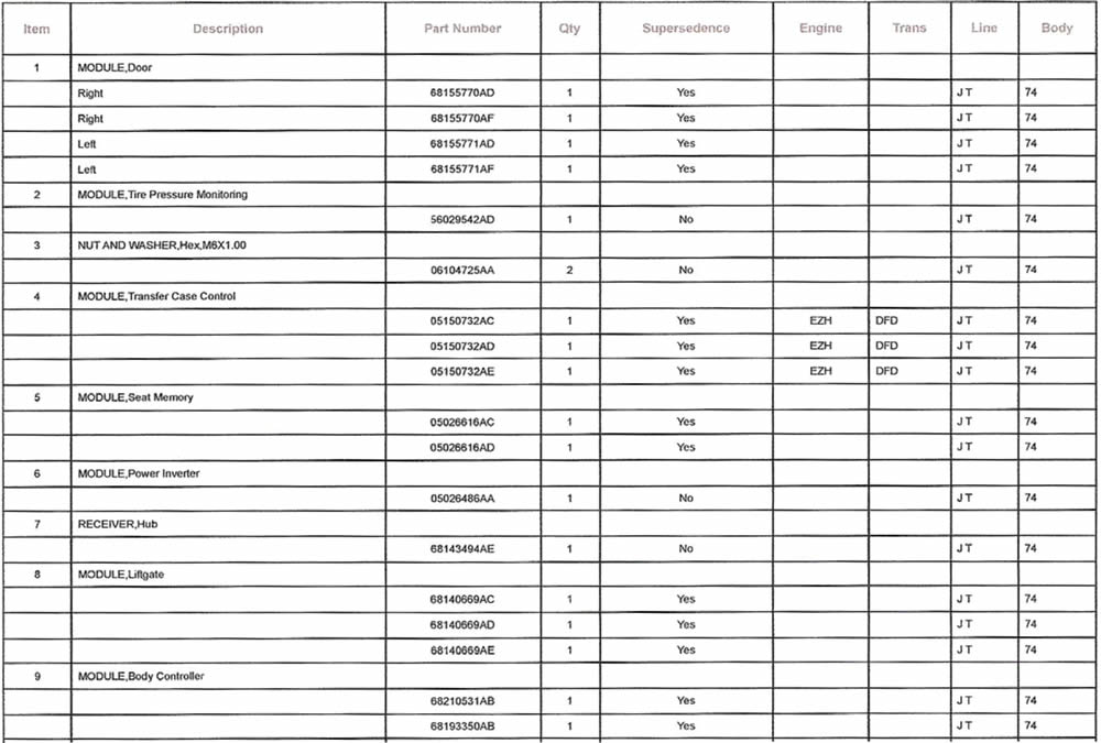
Figure 1: Align slot in shift shaft in case with area marked with red, then follow procedure to install position sensor.
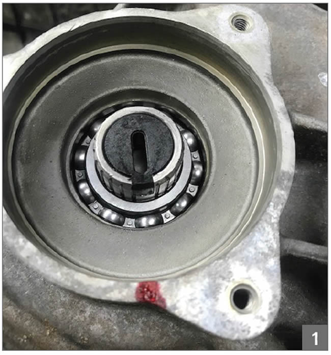
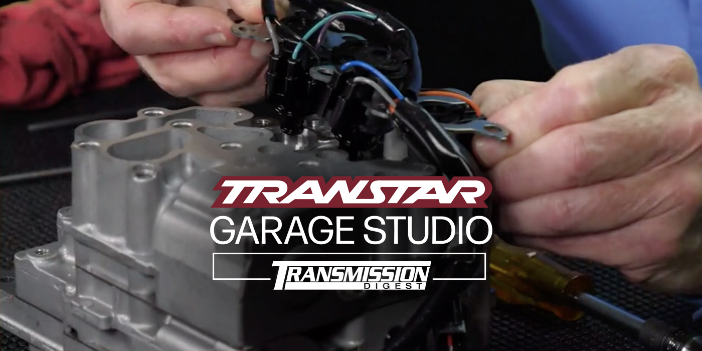
Figure 2: Position sensor installed on case. Turn CLOCKWISE UNTIL BOLT
HOLES ALIGN and then torque attaching bolts.
Figure 3: Case side view of position sensor with shaft lined up with hashmark on brass part of sensor.