Up To Standards
- Author: Mike Weinberg, Contributing Editor
- Subject Matter: Manual transmission
- Issue: Diagnosis & service
Mike Weinberg recommends using simple routines to pin-point the cause of a problem.
For whatever reason, the tech lines get an inordinate number of calls regarding a few specific issues. That such a high volume of calls is generated by just a few problems leads to the belief that we need to revisit and speak about the lack of understanding by the technician that leads to all this wasted time and phone traffic, as well as failure to get the job right the first time. Let’s start out the year by getting to the nittygritty of why certain issues seem to confuse so many people.
Tire sizes
It would seem obvious that with the complexity of late-model transfer cases, transmissions and differentials, everyone would have gotten the memo that tire size (circumference) has to match within 1/4 inch on all four wheels and that the tire pressures need to be equal on all four wheels.
You begin any computer diagnosis of a vehicle by first checking the battery voltage. If the battery is not fully charged, you can never get reliable results from a scan, and false codes are endlessly possible. It takes a few minutes to determine the voltage with an ohmmeter, and you proceed with the rest of the diagnosis. Why not make tire diameter and pressures part of a similar diagnostic protocol on every vehicle you work on? Using a stagger gauge (which is a large direct-reading caliper you can own for around$50) you can get the circumferences on all four tires in five minutes.
Tires that are mismatched by more than 1/4 inch will make computer-controlled transfer cases throw all kinds of problems and codes. Mismatched tires will cause damage to differentials, as the pinion gears are acting as though they are in a turn all the time. Mismatched tires will fail clutch packs, and viscous couplings in transfer cases and differentials in short order. Front-wheel-drive transmissions that contain the ring gear and differential will fail because of mismatched tires. If such a quick, simple item to check as part of your vehicle inspection routine doesn’t become part of your process, you are either beyond help or suicidal.
Clutch release
The major failure of clutch components and, subsequently, the manual transmission involved is an improper clutch release. This can best be described as the failure of the clutch components, either hydraulic or mechanical, to allow a 0.050-inch air gap between the clutch disc and the engine flywheel. Without the ability to disconnect the engine torque from the gearbox, the clutch disc will degrade and overheat rapidly, and since there is no real disconnect to the gear train in the transmission all the torque load will beat the synchronizers and speed gears into an early grave.
There are many reasons why the clutch disc will not release: improperly bled hydraulics, cable adjustments that cannot hold the correct release because of failed components, flexing firewalls, or worn clutch forks or pivot balls. Seized or worn pilot bushings or bearings and bent or rusted clutch discs will all create this problem. Concentric slave cylinders that are mounted inside the bellhousing may have to be shimmed to apply the proper pressure and throw to fully release the clutch disc to en-sure smooth, clash-free shifts. This is the No. 1 villain for clutch and transmission damage and needs a lot of attention and inspection to prevent comebacks and ensure your customer’s satisfaction.
Transfer-case electric-motor replacement
Many times an electronic shift motor needs replacing. The problem occurs when the motor is removed without the transfer case being in the correct position to accept the new replacement motor. On many electronically shifted late-model transfer cases, there is no detent to hold the internal rooster in the correct position. Inside the shift motor is a “motor brake” that acts as a detent to hold the desired mode or range. When replacing a motor where the original was not in the correct position, you have to release the motor brake to achieve the correct position. This can be done by locating the proper circuit schematic for the motor brake and using a nine-volt (smoke detector) battery to energize the circuit and release the brake, allowing proper positioning of the motor. Do not turn these motors too far or you will be buying another one.

Lubrication
Many shift complaints are generated by using incorrect lubricants and lubefill quantities. The friction coefficients of modern synchronizers and automatic transmission and transfercase clutch packs demand specialized specific lubricants. I know it is 4 p.m. on a Friday and the customer wants his car, but if you do not have the correct specified oil, don’t make substitutions.
The nonsense to get it right later will be expensive. Too much oil is no good as it puts the gear train into a heavy windage condition, causing notchy shifts and overheating the unit. Too little oil allows the gear train to run dry under acceleration and braking as the fluid shifts inside the case.
We carry a complete line of our own fluids that we manufacture to the highest standards for synthetic lubrication. We never intended to be in the oil business, but making sure our customer can have the correct oil for the unit he is buying or building at a price better than the dealer’s became a must. Make sure you look at the correct lube specs for the unit you are working on and have it ready to go into the gearbox so you can end some really nagging problems.
Proper differential setup
We get an inordinate amount of call traffic regarding ring and pinion setup and noise complaints, particularly on Dodge 9.25-inch rear ends. These gear sets are priced very high from the dealer, and the aftermarket has many options for OEM-quality aftermarket gears at reasonable prices. There have also been many advances in gear-cutting technology that have changed the way the ring and pinion must be set up for noiseless long-term operation.
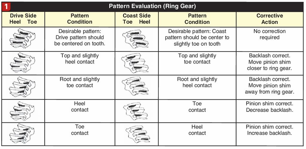
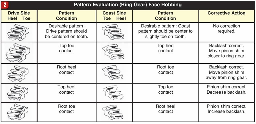
The older manufacturing process used a five-cut system called face milling to make the gear set. A face-milled gear set will have a wider face at the heel of the gear than at the toe. The new method of manu-facture is the Phenix or two-cut system called face hobbing, which produces a gear that has equal depth from heel to toe. The reason you need to know this is that the backlash setup is much tighter on a face-hobbed gear than on the old five-cut gear.
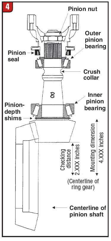
In rough numbers a face-milled gear will typically require 0.0008 inch backlash, while the face-hobbed gear will typically set up with 0.004-0.008 inch of backlash. Pinion depth also will vary. The quality standards of today’s manufacturing will usually allow you to use the original pinion shim with the new pinion gear and get the correct pinion depth. However, with different gears (face milled or face hobbed) this may not hold true. If you are going to do any number of ring-and-pinion installations, you need to have a pinion-depth gauge to be precise. Measuring the depth (thickness) of the old pinion gear from the bearing step to the end of the gear where the head stamp is printed and comparing that with the same measurement on the new gear will give you a close idea of any plus or minus you need on the pinion shim, but nothing beats a pinion-depth gauge for accuracy.
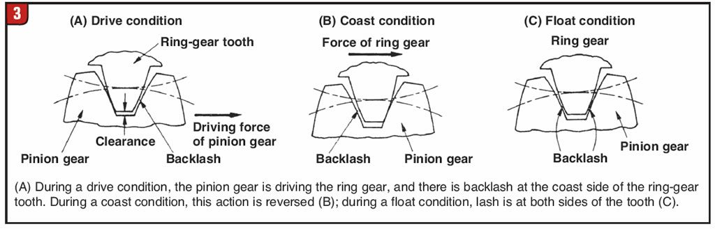
A second tool you will need is a set of new differential and pinion bearings on which you will bore out the internal race by 0.003-0.004 inch to eliminate the press fit. This will become your “setup” set, which will allow you to make shim changes in seconds without the risk of damaging the new bearings in the press. Once you have established that your pinion depth and backlash are correct, remove your setup bearings and press on the new bearings. Refer to figures 1-5 to further understand the relationship between pinion depth and ring-gear backlash.
All the problems we face can be solved with an understanding of the technology and with simple routines to pinpoint the exact cause of the problem. The correct process simplifies your day and will create guaranteed results.