
Up To Standards
- Author: Mike Weinberg, Contributing Editor
The past decade has produced phenomenal growth in sophisticated automotive technology. We are just now beginning to see the huge advances possible in automotive design and function as computer control is reaching higher levels of perfection.
Transfer cases have evolved from simple mechanically shifted units providing four-wheel drive to electronically active units. The goal of the designers has been to create an “automatic” mode of torque transfer to the front and rear wheels without driver involvement. This gives the driver the choice of pulling the transfer case into what is called a “full-time” position, in which torque is transferred to the rear wheels so that the vehicle can be driven at slow or highway speeds with better fuel economy and little or no wheel hop or steering bind in turns.
The early mechanical “active” systems used a viscous coupling or differential within the transfer case to send torque to the front axle when needed. The NP 229, 249 and 242 transfer cases are examples of mechanical active transfer cases. These systems work but are hardly seamless.
As the cost and luxury of SUV models continued to climb, the new buyers of these models put more pressure on the engineers to perfect the active transfer cases through electronic controls. The Dana 28, New Venture Gear 236 and 246, and the BorgWarner 4405 are examples of electronically controlled active transfer cases.
The newest design level in the active transfer case is the NVG 226. GM introduced the Trailblazer, Envoy and new Bravada models that feature a newly designed straight six-cylinder engine. This engine has very high horsepower and torque output and is arguably the smoothest-running straight 6 ever produced. In order to complete this almost vibration-free package, GM chose the NVG 226 transfer case.
Because of the complexity of the electronic control system, this will be a two-part article. This article is an overview of the NVG 226 theory of operations, and next month we will discuss electronic controls and diagnostic methods. If you look at the service manual you will see that the mechanical side of the transfer case is simple and that the diagnostics and electronics cover three times as many pages as the rebuild section.
The NVG 226 transfer case has five operational modes: Auto 4WD, 4 High, 4 Low, 2 High and neutral. The “active” mode is achieved in Auto 4WD mode by using an electronically applied wet clutch to bias torque from the rear wheels to the front wheels as needed. The normal duty cycle is 0-5 lb.-ft. of torque to the front wheels at low speeds and low-torque conditions, and predetermined higher levels of torque transfer for speeds over 20 mph.
The key to this is the ability of the computer control to learn through adaptive logic. The software is capable of adapting to clutch wear and is able to recalculate clutch preload torque levels. This software flexibility is similar to the TF 604 clutch-apply strategy. There is no need to shim the clutch pack to adjust for clutch clearance, as the software learns which position to place the clutch-apply fork in for a seamless clutch engagement as the clutches wear.
The NVG 226 has an aluminum case and extension housing, and all shafts are supported by ball bearings. There are no snap rings retaining the shafts to the bearings. The internal linkage has a dual-purpose “rooster comb” that shifts the unit into the different modes and applies the clutch fork to send power to the front wheels.
This design is different from that of the NVG 236 and 246 transfer cases. In these previous models the clutch fork applies the clutch pack to the rear of the transfer case (rear output shaft). This puts a heavy thrust load on the rear output-shaft bearing, and bearing and case failures are common. The 226 fork apply is toward the front of the transfer case (input-shaft side), and the front of the mainshaft is supported in the input gear by a thrust bearing.
A planetary gearset provides gear reduction for low-range off-road operation. The NVG 226 is filled with two quarts of Auto Trac II fluid, GM part # 12378508, which is blue. The clutches, which are lined on only one side, have a co-efficient of friction designed for this lubricant. Chatter and clutch failure will occur if you substitute fluids. Lubrication for this unit is pressurized and is provided by a gerotor type of pump in the rear case half, driven by the rear output shaft.
This transfer case uses an electronic motor and encoder both to shift the unit and to apply the clutch pack when needed. In past designs the motor and encoder are one integrated assembly. In this unit the encoder is housed at the base of the motor and is replaceable separately. The encode performs the same functions as a manual-lever-position sensor by signaling the computer the position of the motor shaft. This motor is contained in an aluminum housing with multiple sets of small planetary gears to provide the torque necessary to apply the clutch pack. Do not disassemble the motor unless you wish to buy a new one.
The 226 is controlled by a computer called the transfer-case control module. When the vehicle is in the AWD mode, the control module monitors road speed through the vehicle-speed sensor, and front and rear driveshaft speeds through speed sensors in the transfer case. When the control module sees a difference of 15 or more rpm between the two propshaft speeds, it engages the clutch pack. When the shaft speeds have equalized the clutch pack is released.
This should tell you that when diagnosing one of these vehicles, the first step you should take is to measure tire pressure and tire diameter. If the tire sizes and pressure are not equal on all four wheels, the control module will set a diagnostic trouble code.
Another interesting fact about the transfer-case control module is that it does not know what vehicle it is in. The vehicle identification number must be entered into the control module so that it can choose a software parameter that matches the vehicle’s axle ratio, transmission, tire size and engine.
Instead of having separate control modules for every variation in vehicle options, the software is present for all possible configurations within the control module. If you have to replace a failed control module, you must use a scan tool to input the VIN into the new module so that it can choose the correct software for the vehicle.
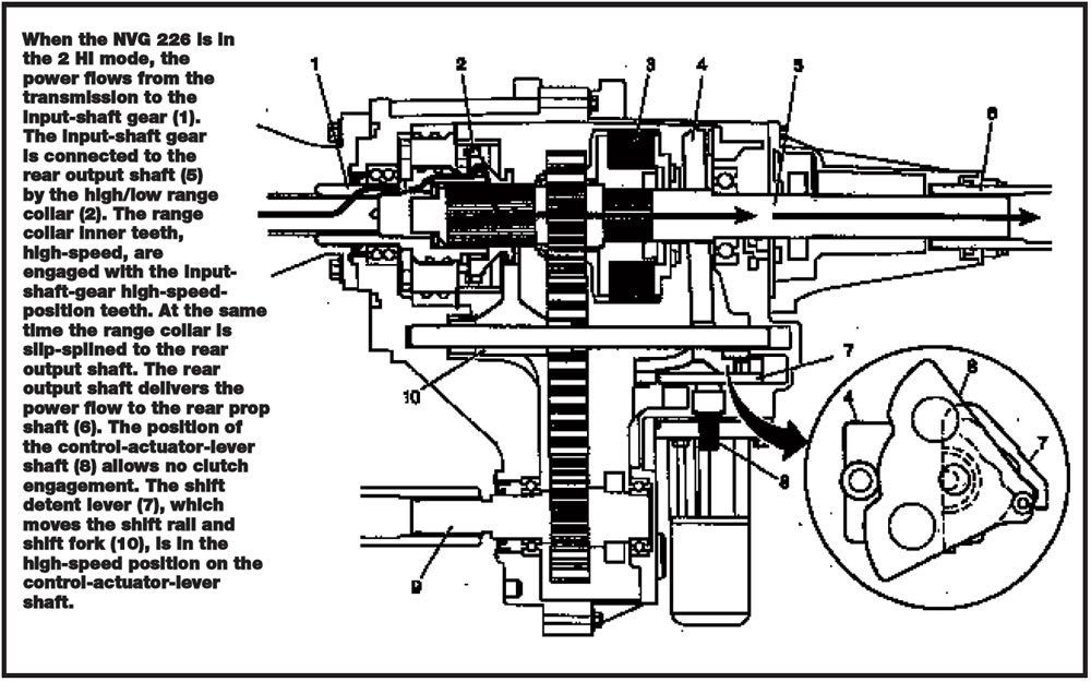
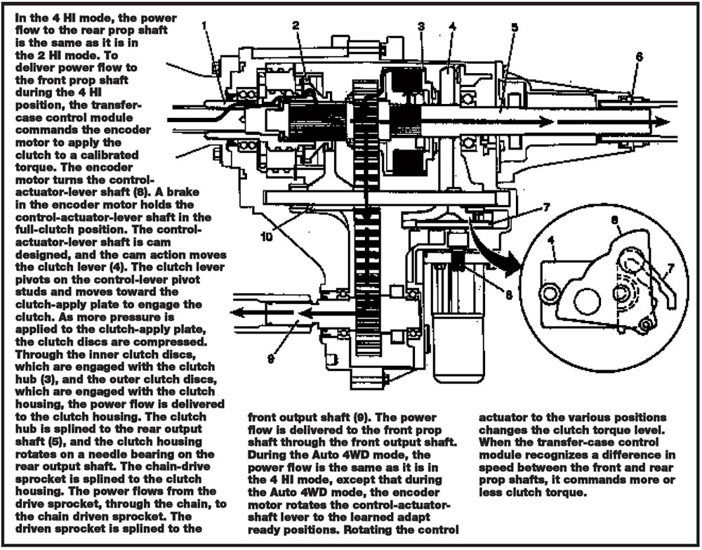
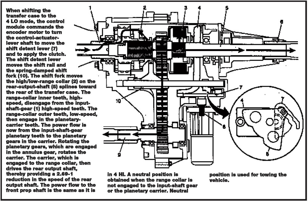
I have included the power-flow charts for the various operational modes here. Understanding the power flow is the first step in successful diagnosis. Next month we will look at the electronic functions, diagnostic routines and DTC descriptions.