Up to Standards
- Author: By Mike Weinberg, Contributing Editor
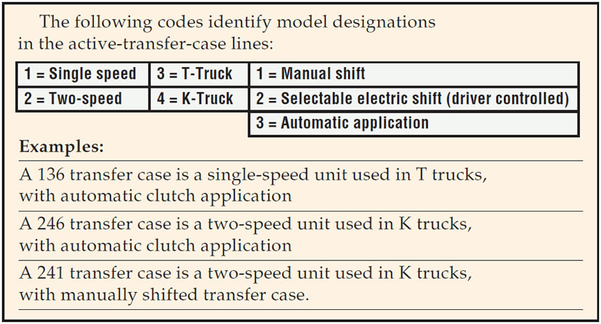
The New Venture 246 transfer case has been around since the 1998 model year. Found in GM K trucks (Tahoe, pickup, Yukon, Suburban, Suburban EXT, Escalade and Avalanche), this is a large, heavy-duty transfer case.
This line of transfer cases is referred to as ATC, which stands for “automatic transfer cases” or “active transfer cases.” The automatic or active transfer case designates the design capability of these units to alter the amount of torque sent to the front axle when the computer senses wheel slip without any input from the driver.
Using an internal clutch pack and relying on speed sensors that monitor the speeds of both axles and the propshafts, the ATC control module (computer) will send from 5% to 95% of available torque to the drive wheels that need it. When the wheel-slip event is gone, the ATC module will release the clutch pack, restoring 95% of torque to the rear wheels.
It is easy to see that any external variations in wheel or tire size or tire pressure can fool the computer into detecting a slipping condition. Before doing anything else on one of these vehicles you must make sure that all tires are of the same measured circumference and that the tire pressures are equal on all four wheels. A difference of 15 rpm between front and rear propshaft speeds can activate the clutch pack or set DTC codes. This translates into a difference in tread wear of 1/16 inch. There is no room for error here, and if you neglect to measure the tires with a stagger gauge or a tape measure around the center of the tire, this unit will turn into a diagnostic nightmare.
This is a complex operating system and is not well understood in the field, which leads this unit to create exceptionally high amounts of traffic on our technical help line. This article is meant to give you an overview of the operating system to help simplify diagnosis and repairs.
Shift modes
- Auto – In this mode the ATC module will vary the torque available to the front axle as needed without intervention by the driver. The front-axle actuator is always engaged, locking the front propshaft to the front differential.
- 2WD – In this mode the 4WD operation is disabled and the front propshaft is disconnected from the front differential. There are no active or automatic functions in 2WD.
4WD High – The transfer case is fully engaged to both axles with a 50/50 torque split. This mode should be used only on snow- or ice-covered roads and never on dry pavement, or else crow hop and wheel chatter will begin. - 4WD Low – Creates the same conditions as 4WD High, except that power now flows through a planetary gear set, providing a 2-1 gear reduction. This mode is for off-road use only and should never be used on dry pavement.
- Neutral – There is no power flow through the transfer case, allowing the use of accessories or flat tows for short distances. There is no button for Neutral. To get into neutral, the driver presses the 2 High and 4 High buttons at the same time and holds them for at least 10 seconds. Vehicle speed must be less than 3 mph, the transfer case must be in the 2 High range, the transmission must be in neutral or the clutch depressed, and there must be a speed signal from the engine.
The NV 246 has the following control components:
- ATC module
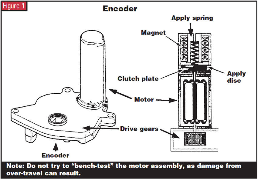
- An encoder with a pulse-width-modulated controlled shift motor and motor brake. This multifunction unit has the ability to shift the transfer case into different modes, apply and release the internal clutch pack, and lock the motor to a determined position.
- Three vehicle-speed sensors
- A throw-out bearing within the transfer case
- An internal multiple-disc clutch pack
- Vehicle-control-module (VCM) interface
- ATC-control-switch assembly mounted in the driver compartment.
To diagnose and repair one of these active transfer cases properly, you must have a scan tool. You also will need to access the proper diagnostic reference material online to obtain codes, wiring diagrams and other necessary information. The scan tool also can be used to activate various circuits for voltage and resistance readings and to make sure the ATC module is flashed properly for the vehicle it is in. If you need to replace an ATC module you must use the scan tool to program the new ATC module to the vehicle you are working on, or else it will not be able to communicate with the VCM interface.
Scan-tool-data definitions
- 2WD High indicator light – The scan tool will read on or off and should indicate on when the transfer-case shift-control module (TCSCM) asks for 2WD high mode.
- 4WD High indicator light – The scan tool will read on or off and should indicate on when the TCSCM asks for 4wd High mode.
- 4WD Low active – The scan tool shows yes or no. It should indicate Yes when the transfer case is in the 4WD Low lock mode.
- 4WD Low indicator light – The scan tool shows on or off. It should read on when the TCSCM commands 4WD Low mode.
- ATC application – The scan tool will display a numeric value indicating the model number assigned to the transfer case.
- ATC software ID – An alphanumeric value will be displayed, indicating the numbers or characters assigned to the current version of software used by the TCSCM.
- Auto 4WD indicator light – The scan tool shows on or off. It should display on when the TCSCM commands the Auto 4WD light on.
- Battery voltage – A voltage reading of 0-25.5 volts will display, indicating the voltage measured by the TCSCM at the TCSCM battery feed.
- Current slip adapts – A numeric value displayed by the scan tool that indicates the corrective adjustments being made by the control module for wheel-slip occurrences. Note: This is useful in helping to determine whether tire size or pressure is causing codes to set.
- Encoder Gear Position – The scan tool will display the mode in which the transfer case is operating.
- Encoder Return Voltage – The scan tool will display the voltage that the ATC module sees at the encoder signal return. The voltage will be 0-7.5 volts. Never put battery voltage to the encoder unless you wish to buy a new one.
- Encoder Supply Voltage – This indicates voltage seen by the ATC module at the encoder power supply. The scan tool will display 0-7.5 volts. Again, never put battery voltage to the encoder unless you wish to buy one.
- Front Axle requested – The scan tool will show yes or no. Yes should be displayed if the ATC module has commanded any range besides 2W High or Neutral. If the scan tool shows yes, the front-differential actuator should lock the front driveshaft to the front differential.
- Front Axle switch – The scan tool will read locked or unlocked, indicating the state of feedback of the front propshaft.
- Ignition Cycles Since Last Current DTC – The scan tool will display a numeric value indicating how many ignition cycles have occurred since the latest current DTC.
- Mode Switch Return voltage – A reading of 0-5 volts, which indicates return voltage from the transfer-case control switch.
- Mode Switch Selected – The scan tool will display the current mode selected, and this should match the shift-control-switch button pressed by the driver.
- Motor A Current – Amperage displayed on the scan tool indicates the flow of current when the motor moves in one of two directions.
- Motor B Current – Amperage displayed on the scan tool indicates the flow of current when the motor moves in one of two directions.
- Neutral indicator light – The scan tool will read on or off. On should be indicated when the ATC module commands the neutral position.
- Rear Propshaft Speed – Indicates the rotational speed of the rear propshaft; the scan tool will display 0-8,192 rpm.
- Service 4WD Lamp – The scan tool will read on or off. On indicates that the ATC module has commanded the Service 4WD lamp or message on.
- Slip Adapt PWM – Indicates the duty cycle applied to the transfer-case encoder motor for clutch application. The scan tool will display 0-100%.
- Total Slippage – This indicates the total slippage of both front and rear propshafts and will be displayed as 0-8,192 rpm.
- Transfer Case Lock – The scan tool will show enabled or disabled and should indicate enabled if the ATC module commands the transfer-case-motor brake on. If the motor brake is on, rotating the encoder motor by hand is impossible.
Scan-tool output controls
The scan tool can be used to control many of the transfer-case functions for diagnosis and testing. The scan-tool output controls may require additional menu selections to access all the functions.
- 2WD High indicator light – Allows technician to turn on or off the 2WD High light on the TC control switch.
- 4WD High indicator Light – allows technician to turn on or off the 4WD High light on the TC control switch.
- 4WD Low indicator Light – allows technician to turn on or off the 4WD low light on the TC Control switch
- ATC Motor A Control – permits the technician to shift the transfer case through all five modes. Motor Control A moves in the opposite direction of Motor Control B.
- ATC Motor B Control – permits the technician to shift the transfer case through all five modes. Motor Control B moves in the opposite direction of Motor Control A.
- Auto 4WD indicator light – allows the technician to turn Auto 4WD light on or off on the transfer-case control switch.
- Engage Front Axle – Permits the technician to engage or disengage the front-axle actuator. When engaged, the actuator should lock the front propshaft to the front differential.
- Neutral indicator light – allows the technician to turn the neutral indicator light on or off on the transfer-case control switch.
- Transfer Case Lock – Allows the technician to turn the encoder-motor lock on or off. With the encoder-motor lock on, shifting the transfer case is impossible. Note: This is an important function to access when you’re replacing an encoder motor. With the lock disabled you will hear a click, and you can move the encoder motor by hand to line up with the shift lever when replacing an encoder motor. Be extremely careful when rotating the encoder motor by hand not to over-rotate the motor or it will need to be replaced. An alignment tool supposedly is available, but as of this printing I have not been able to find a part number.
Diagnostic procedures and trouble codes
To diagnose and test these transfer cases properly you must have a proper scan tool and access to online diagnostic information. I will give you an overview of the codes, but there isn’t room here to go through the test procedures to solve the problems. Begin all diagnostic routines by accessing the Diagnostic System Check-Transfer case. This will review three important areas through the scan tool. It will identify the control modules that are in command of the system, it will check the ability of the control modules to communicate through the serial data circuit, and it will identify any stored DTCs and their status.
The 246 has at least 19 available trouble codes. Where many technicians get into trouble is in identifying which codes work with which system. None of these codes is a powertrain code. They are chassis, body and universal codes and are identified by the letter prefix of the code. “C” is a chassis code; “B” indicates a TBCM (truck body-control module) circuit failure; and “U” codes, known as universal DTCs, indicate a data-transmission-network concern.
DTC # Description
- C0300 Rear vehicle-speed sensor
- C0305 Front vehicle-speed sensor
- C0308 Motor A/B circuit low voltage
- C0309 Motor A/B circuit high voltage
- C0310 Motor A/B circuit open
- C0315 Motor ground circuit high resistance
- C0323 T/case lock circuit low voltage
- C0324 T/case lock circuit high voltage
- C0327 Encoder circuit
- C0357 Park-switch circuit high voltage
- C0362 4 Low circuit low voltage
- C0367 Front-axle circuit high voltage
- C0374 General system malfunction
- C0376 Front vs. rear propshaft speed incorrect
- C0550 ATCM processor malfunction
- C0611 VIN information incorrect
- C0895 Voltage incorrect
- B0768 Service light low voltage
- B2725 Mode-switch malfunction
- U1016 VCM communications
- U1041 EBCM communications
- U1064 TBCM communications
Encoder motor: important information
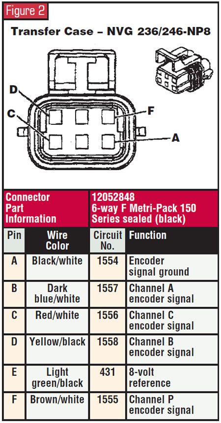
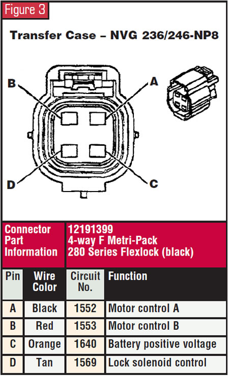
The encoder motor is a complex design. There are two electrical connections, one six-pin on the motor and a four-pin pigtail, for which I have provided pin schematics in the illustrations here. Never put 12 volts to this system. This system is designed to handle a 5-volt reference and 7.5 volts for operating power. The encoder motor provides several functions: It shifts the transfer case through the five modes, applies the clutch pack and informs the ATC module of the mode in which the transfer case is operating.
When you are going to disassemble the transfer case, make sure it is in 2WD High mode before removing the encoder motor. Failure to do so will require releasing the encoder-motor brake before you replace the encoder motor on the transfer case to index the motor to the shift rail correctly. You can do this with a scan tool and the motor plugged into the harnesses. It also possible to do this on the bench. You will need a 9-volt radio battery and two leads. Connect the positive lead to pin C (battery positive voltage) on the four-pin pigtail (orange wire) and the negative lead to pin D (lock control circuit), the tan wire. You should hear a click and be able to rotate the motor by hand. Use extreme caution not to over-travel the motor or else it will be expensive junk.
These are sophisticated transfer cases, as one would expect from the price tags of the vehicles in which they are used. A complete understanding of their function and electronic controls should make diagnosis and repairs quicker and easier to achieve. Welcome to the computer world, where information is the most-important commodity.