Up to Standards
- Author: Mike Weinberg, Contributing Editor
Chapter 2
In the previous issue we discussed the theory of operations of the New Venture Gear 226 transfer case, which is found in the GMC Envoy, Chevrolet Trailblazer and Oldsmobile Bravada. This chapter is devoted to helping you to get familiar with the electronic functions of this “active” transfer case.
Before we go on, there is a trap that too many technicians fall into when beginning the diagnostic procedures for any mechanically or electronically active transfer case. A mechanically active transfer case is one that has a full-time mode that uses a viscous coupling or an internal differential in the transfer case to permit 4WD operation at highway speeds on dry pavement. If you get nothing else from this article, commit the following to memory: Before beginning any type of diagnosis on any “active” transfer case, make sure the tire pressures are equal on all four wheels, and make sure that all four tires have the exact same circumference. A 1⁄4-inch difference in tire circumference or a difference of a few psi in tire pressure will set codes, cause mechanical units to wheel-hop in turns, burn up a new viscous coupling or cause a mechanical unit to remain locked in 4WD with the shifter in the 2-high position. Just as you would never begin a diagnostic routine on a computer problem without first checking battery voltage, checking tire pressure and size is the first step to take. There is not a week that goes by without our hearing from a shop that has taken a perfectly good transfer case apart because the technician did not check tire pressure and size.
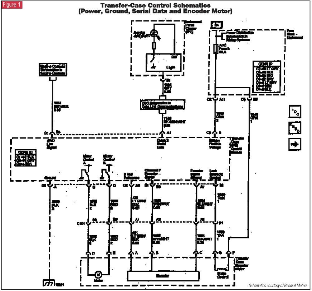
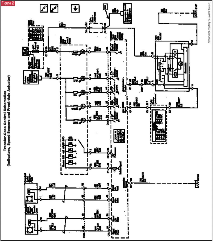
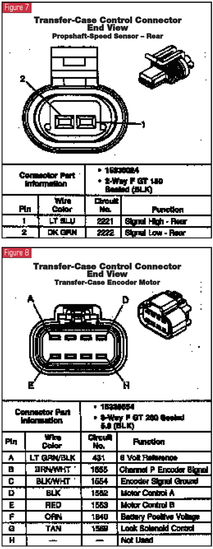
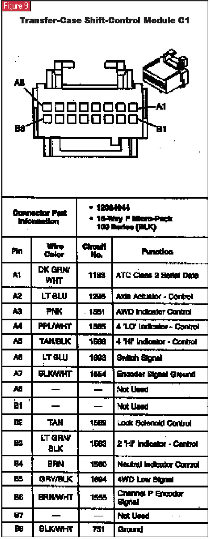
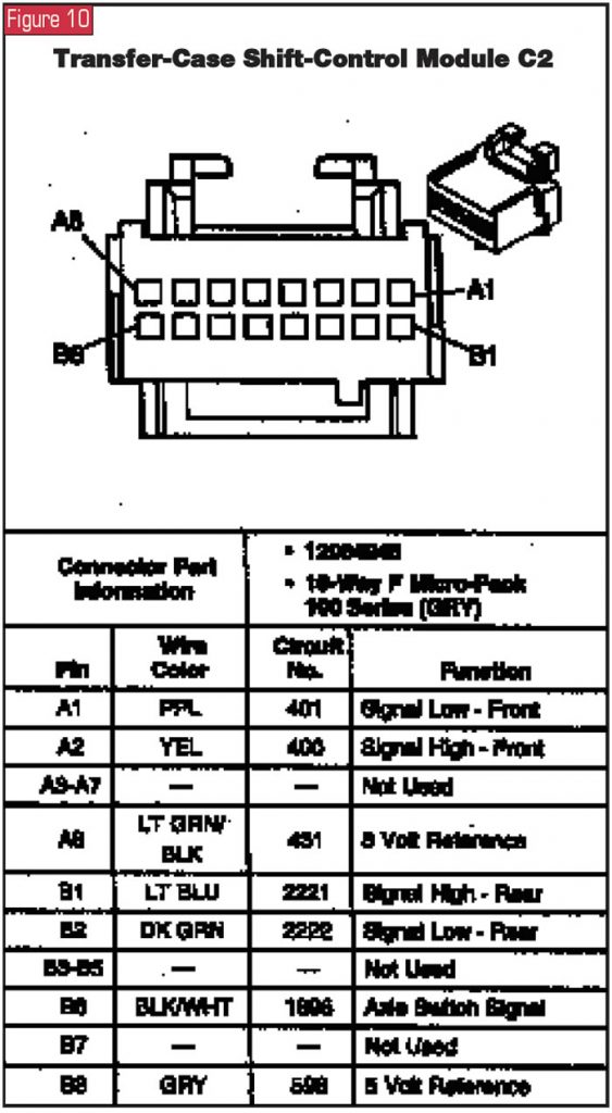
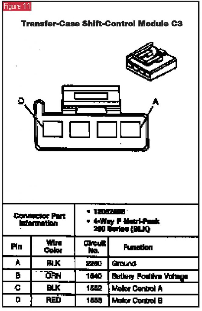
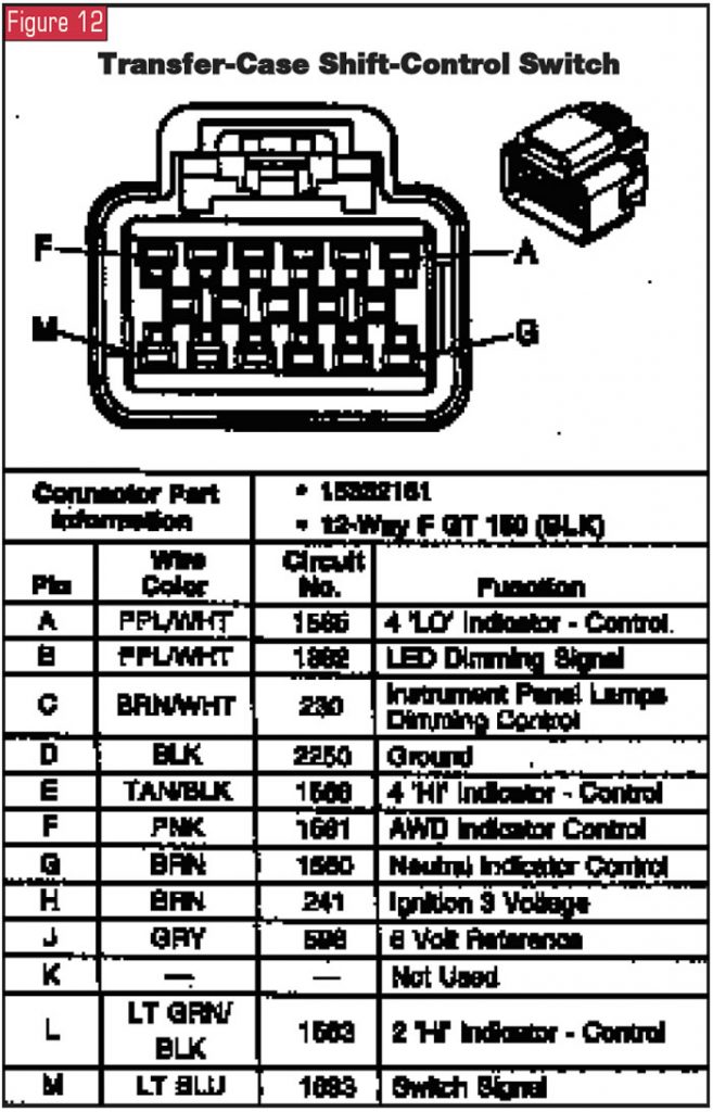
You will need the service manual when diagnosing the NVG 226. I have provided a number of wiring diagrams and parts locations here, but we are only scratching the surface. The electronic functions have become very complex and sophisticated, with the transfer-case shift-control module (TCSCM) communicating with more than one onboard computer through a serial data bus. The good news is that the diagnostic programs also become very sophisticated and allow you to monitor everything that the TCSCM “sees.” When diagnosing the NVG 226, begin by performing the transfer-case diagnostic-system check, and always repeat this check procedure after completing any repairs. This transfer-case diagnostic-system check is outlined in the service manual and allows you to quickly check the 4WD indicator operation, check the ability of the TCSCM to communicate with other vehicle computers and the data-link connector, and show you any current or history DTCs stored in memory.
There are 31 parameters of operation that the scan tool can display. This information is displayed by name so that you can understand the feedback obtained through the scan tool.
- ACTIVE AWD MODE – lets you see whether the AWD mode is active. The scan tool will read YES or NO.
- ATC CALIBRATION PART # – This number displayed on the scan tool is the part number assigned to the current version of ATC module calibration.
- ATC HARDWARE PART # – The scan tool can display the part number of the ATC control module.
- ATC JULIAN DATE – The scan tool indicates the production date of the ATC module.
- ATC PART # – The number displayed on the scan tool is the GM part number given to the module package including the software, calibrations and module.
- ATC SLIP SPEED – The scan tool will display the difference in speed between the front and rear prop shafts. The speed range is from 0-8,192 rpm.
- ATC SOFTWARE PART # – The number seen on the scan tool is the part number of the current software level used in the ATC module.
- AUTO 4WD INDICATOR LIGHT – The scan tool will show on or off. This informs you whether the Auto 4WD indicator light is being enabled by TCSCM.
- BATTERY VOLTAGE – The scan tool will display the voltage seen by the TCSCM at the battery feed.
- CLUTCH PEDAL ENGAGED – Yes or No on the scan tool indicates whether the clutch pedal is engaged or disengaged on vehicles equipped with manual transmissions.
- CURRENT SLIP ADAPTS – The number displayed on the scan tool shows the amount of compensation being made by the TCSCM for wheel slippage.
- ENCODER GEAR POSITION – The scan tool displays which mode the active transfer case is in.
- ENCODER RETURN VOLTAGE – The reading on the scan tool will range from 0 to 25.5 volts, which is the voltage seen by the TCSCM at the encoder return signal.
- ENCODER SUPPLY VOLTAGE – This is the voltage seen by the TCSCM at the encoder power circuit. Voltage will range from 0-25.5 volts.
- FRONT AXLE REQUEST – A Yes or No reading on the scan tool lets you know whether the TCSCM has requested front-axle engagement.
- FRONT AXLE SWITCH – Locked or Unlocked on the scan-tool screen shows the status of the front driveshaft.
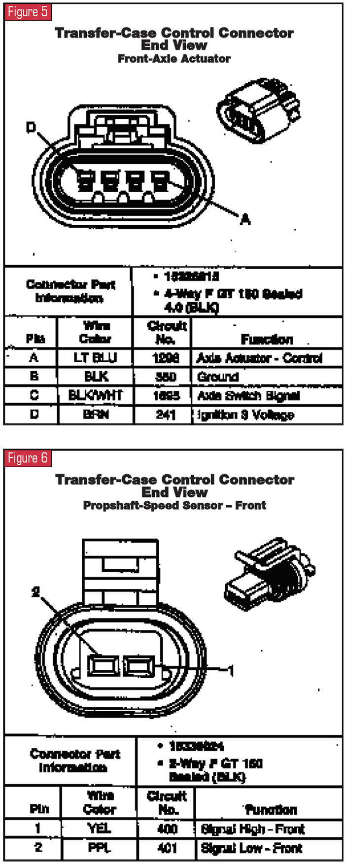
- FRONT PROP SHAFT SPEED – The scan tool indicates the speed of the front driveshaft as measured by the front-propshaft speed sensor in the transfer case.
- IGNITION CYCLES SINCE LAST CURRENT DTC – The number shown on the scan tool will be how many times the ignition has been cycled since the last current DTC was stored.
- MODE SWITCH RETURN VOLTAGE – A 0-25.5 reading on the scan tool measuring the return voltage from the mode switch.
- MODE SWITCH SELECTED – The scan tool shows the ATC-mode switch button presently depressed by the operator. The reading will show On or Off.
- NEUTRAL INDICATOR LIGHT – Read as On or Off by the scan tool, indicating if the TCSCM is commanding the Neutral Indicator light on or off.
- REAR PROP SHAFT SPEED – This measures the speed of the rear driveshaft as measured by the rear speed sensor on the transfer case. Speed will range from 0 to 8,192 rpm.
- SERVICE 4WD LAMP – The display on the scan tool will show On or Off so that you can verify the working status of the 4WD light.
- SLIP ADAPT PWM – The scan tool will show the percentage of duty cycle being applied to the ATC motor, reading from 0 to 100%.
- TOTAL SLIPPAGE – The scan tool indicates the total slippage of the front and rear driveshafts, with a range of 0-8,192 rpm.
- TRANSFER CASE LOCK – Enabled or disabled on the scan screen, advises the tech whether the TCSCM is commanding the transfer-case motor brake on.
- 2WD HIGH INDICATOR LIGHT – Shows on the scan tool as On or Off. This verifies whether the TCSCM is enabling the 2WD High indicator light.
- 4WD HIGH INDICATOR LIGHT – Shown as On or Off; checks whether the TCSCM is requesting the 4WD High indicator light on or off.
- 4WD LOW ACTIVE – Shown as Yes or No; the scan tool shows whether the 4WD Active Mode is functional.
- 4WD LOW INDICATOR LIGHT – On or Off; shows whether the TCSCM is asking for the 4WD Low Indicator Light to function.
As you can see, the diagnostic parameters in the control module will help you confirm the transfer-case functions using the scan tool. This will quickly lead you to the proper tests to make when a malfunction is found, from the comfort of the cab. It also provides direct measurement of various speeds while you’re test-driving the vehicle. Although this transfer case has very sophisticated controls, it is also easier to diagnose than earlier models with less-advanced diagnostics. Borrow the service manual, and the rest will be fairly simple.