Souza Sezz
- Author: Mike Souza
- Subject Matter: U880E/AF50-8
- Issue: Information
The Aisin Warner AAWF8F45 eightspeed front wheel drive transmission is refered to as the U880E in Toyota/Lexus models and the AF50-8 in GM vehicles. The AF50-8 found in GM and Volvo (TG-81SC) models is equipped with a non-contact type shift position sensor in-U880E/AF50-8 Electronic Information corporated into the TCM (Figure 2). Similar to the range sensor and TCM on the Aisin AF40-6 six-speed transaxle found in some GM, Ford and Volkswagen models. The sensor detects shift position by using a hall-effect type signal that outputs a specific voltage in the P, R, N, D shift position. The magnet position in the sensor changes when moving the shift lever, enabling the Hall IC to convert magnetic field strength into an electrical signal depending on the shift position. Hall IC is an electronic part that monitors movement caused by potential difference when a magnetic field is generated. When a magnetic flux is applied perpendicularly to electric current flowing into a conductor or semiconductor, the potential difference is called hall voltage. It is generated perpendicularly in both the electric current and magnetic flux referred to as “Hall Effect.” The non-contact type sensor does not have contact points like a contact type switch making it very compact and less vulnerable to internal wear.
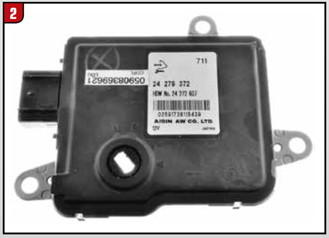
This allows this type of sensor to be integrated into the TCM to improve reliability and durability.
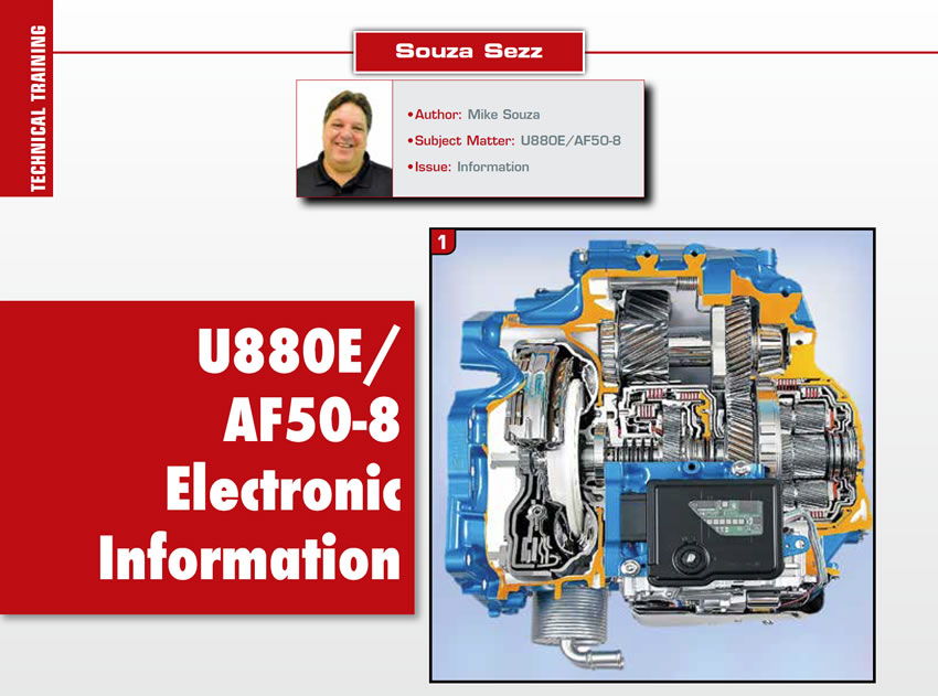
The TCM/range sensor is mounted directly on top of the transmission as shown in Figure 1. The TCM is mounted so that the selector lever shaft goes through the control module.
The selector lever position must be calibrated with a scan tool, there is no mechanical adjustment. An external 16 terminal connector connects to the vehicle’s electrical system (Figure 3). You can see by the TCM pin identifcation legend there are no pins to connect a multimeter for voltage or resistance checks to adjust the range sensor. Only battery voltage, ground and serial data pins for computer communication.

As underneath the control module is another connector (33 terminal) (Figure 4), that connects the TCM directly to the transmission (GM example Volvo is similar). The TCM makes contact with all the transmission solenoids, fluid temperature and speed sensors at this connection. With TCM removed, the legend in Figure 4 will identify which pins to probe with a multimeter for checking the internal electronics.

The TCM is not found on Toyota/Lexus models, there is only a range sensor located on the top of the U880E model transmission.
A gear selector N position learn procedure is required if any of the following components have been repaired, replaced, removed or serviced:
- Transmission Control Module
- Engine Control Module
- Transmission Shift Lever
- Automatic Transmission Assembly
- Shift Lever Cable
The procedure goes as follows:
- Ignition Off.
- Apply the parking brake.
- Block the drive wheels.
- Transmission in Neutral.
- Ignition On, engine Off (Vehicle in Service Mode).
- Perform the scan tool learn function: Gear Selector N Position Learn. Follow the instructions on the (capable) scan tool.
- Ignition Off for more than 10 seconds.
- Ignition On, Engine Off (Vehicle in Service Mode).
- Verify the (capable) scan tool parameter: Transmission Range Switch = Matches the selector lever position.
If this procedure is not performed correctly, the vehicle may not fucntion properly, which could result in a diagnostic trouble code (DTC) P086F neutral position not learned.
If the TCM goes to failsafe, follow each step to the letter if one step is not performed correctly go back to step one of the procedure. The failsafe shift commands are shown in the chart in Figure 6. There are three internal hall effect speed sensors (two-wire type) located on the transmission, all found under the valve body assembly (Figure 7).
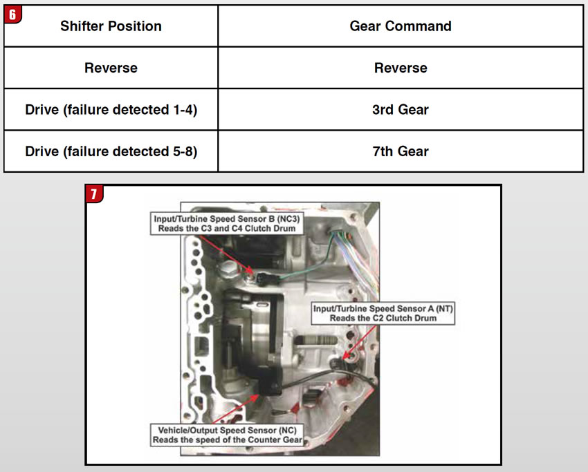
They are referred to as the input/turbine speed sensor A (NT), input/turbine speed sensor B (NC3) and vehicle/output speed sensor (NC).
The input/turbine speed sensor B (NC3) is not found in the GM and Volvo models, only in Toyota and Lexus models. The input/turbine speed sensor A (NT) is located on the center/rear section of the case and it measures the speed of the transmission input shaft by monitoring the indentations of the C2 clutch drum. Vehicle/output speed sensor (NC) is located on the counter gear support under the valve body to monitor the counter gear output speed. The input/turbine speed sensor B (NC3) found in Toyota and Lexus models is located on the upper middle section of the case and it measures the turbine speed by monitoring the openings in the C3/C4 clutch drum.
Thanks for reading the “Souza Sezz” column, see you next time! Let us know what you would like to see future articles cover.


