Shift Pointers
- Subject: Valve body and solenoids
- Unit: 6R140W
- Vehicle Application: Ford Super Duty pickups
- Essential Reading: Rebuilder, Diagnostician
- Author: Pete Luban, ATSG, Transmission Digest Contributing Editor
For the 2011 model year Ford Motor Co. replaced the 5R110W in its Super Duty pickup trucks with a full-time six-speed transmission. Those of us in the aftermarket industry are calling this transmission the 6R140W. Ford likes to call it the TorqShift®6.
Unlike the 5R110W, which was also a six-speed – although, depending on transmission temperature, it would give you only five forward speeds – the 6R140W will provide all six speeds at any given time. Depending on transmission temperature, it will allow converter-clutch operation from first gear on up through sixth gear.
The 6R140W has a pretty gutsy initial take-off due to a 3.97 first-gear ratio.
The factory fluid is Mercon® LV, and dry capacity is 16.2 quarts for trucks equipped with diesel engines and 17.2 quarts for trucks equipped with gasoline engines.
Line pressure for this unit is slightly unusual; 90 psi is the spec in both drive and reverse at idle. Line pressure at wide-open-throttle (WOT) is 230 psi and only 10 psi higher in reverse at WOT for a spec of 240 psi.
Anytime a new transmission comes out we at ATSG usually like to start with the hydraulic control system, so we will start with the valve body in this issue.
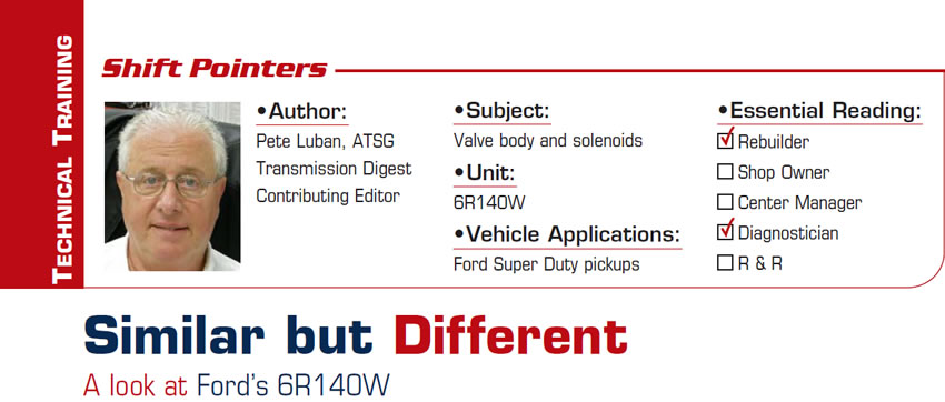
In Figure 1 the solenoids are identified, and as you can see there are seven of them. You can also notice that just like its predecessor this unit has no on/off solenoids. Its solenoids are all regulating types and therefore must be categorized as either normally high or normally low. A normally high solenoid will pressurize its related hydraulic circuit when power is removed. A normally low solenoid will exhaust its related circuit when power is removed.
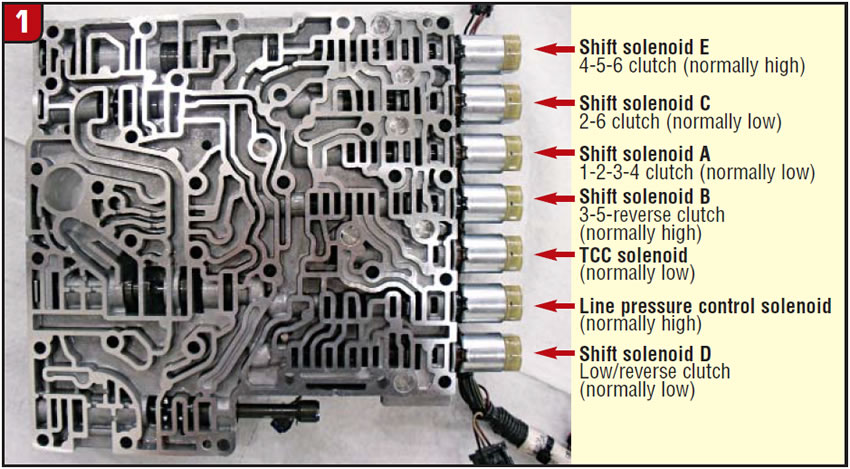
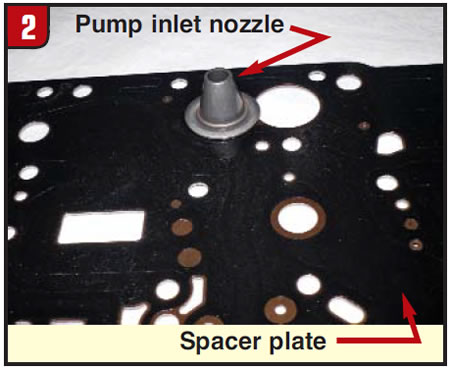
Figure 2 shows a funnel-shaped object stuck to the spacer plate; this is the pump inlet nozzle. Figure 3 shows the valve-body small parts – not a lot going on here. You have two checkballs, two checkvalves and the location of the pump inlet nozzle.
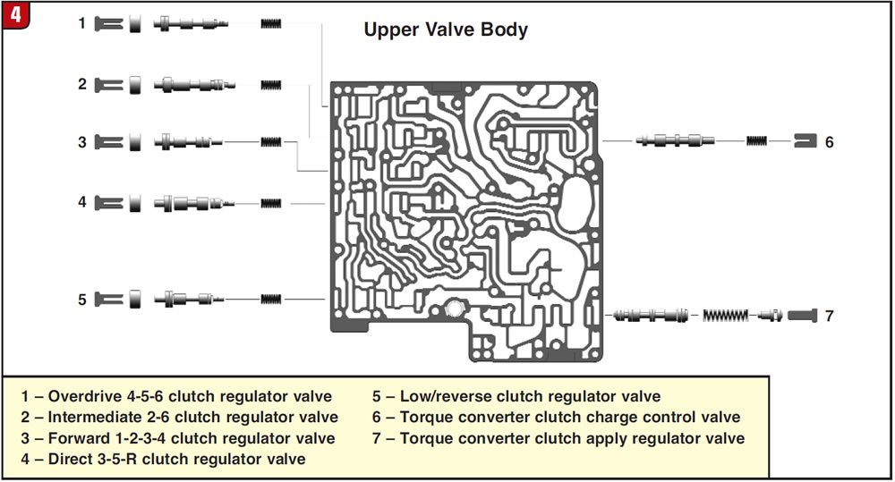
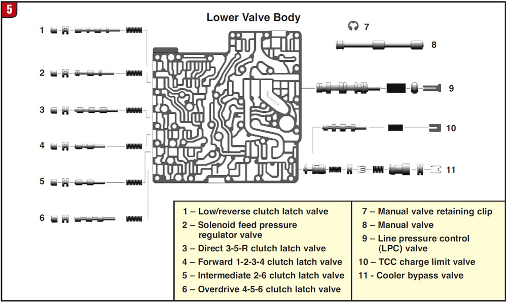
Valve identification for the upper valve body is in Figure 4, and Figure 5 identifies the lower-valve-body valve arrangements.
In the near future we will get deeper into this transmission, especially the hydraulics, as well as all the parts and pieces and the electronic operation, so stay tuned.


