
Preliminary Information
The new Ford 5R110W, referred to by Ford Motor Co. as the “TorqShift” transmission, is a redesign of the 4R100 with some previous strategy applied. This unit was introduced in model year 2003 in the F-Series trucks and Excursions equipped with the new 6.0L diesel engine.
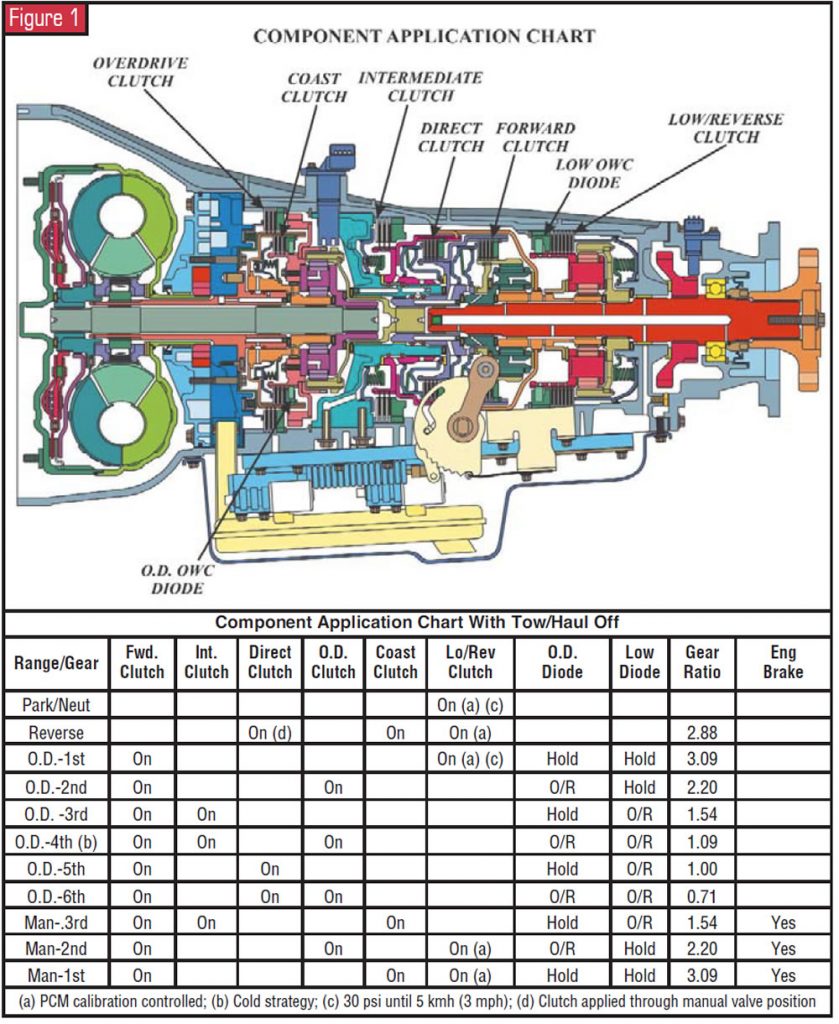
The TorqShift is a five-speed, rear-wheel-drive unit that actually has six forward speeds with ratios depending on whether the transmission is operating in hot or cold mode.. The ratio for 1st gear was changed from 2.71 to 3.09. For 2nd gear the overdrive clutch is applied to provide a ratio of 2.20. 3rd gear provides a ratio of 1.54, the same as the 4R100’s second gear. All sound familiar? In cold mode (below -15°C (5°F), determined by the transmission-fluid-temperature sensor), the overdrive clutch is engaged in 3rd gear to provide a ratio of 1.09 for 4th gear, and the transmission will shift directly from 4th to 6th gear (overdrive), which has a ratio of 0.71. In hot mode the transmission will shift 1st, 2nd, 3rd, 5th (ratio 1.00), 6th.
ATSG’s perception of the 2003 Super Duty vehicle that we test drove was that shift performance is greatly improved over the 4R100 transmission. There were no lags between shifts, and every shift was very positive. This is due to a total redesign of the control valve body. A solenoid and a pressure switch are dedicated to the function of each clutch pack, except the forward clutch, which is controlled by the manual valve. There are no other shuttle valves in the solenoid body.
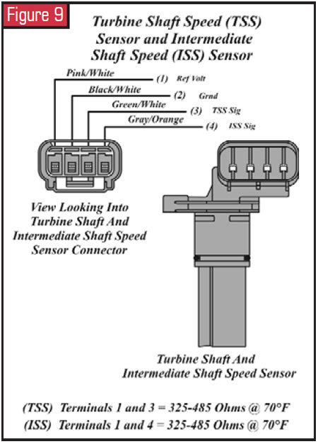
Five solenoids control all shifts. Line pressure and the torque-converter clutch each have their own dedicated solenoid. Four of the solenoids – TCC, OD clutch, intermediate clutch and the low/reverse clutch – are directly proportional, meaning the pressure output is directly proportional to the applied DC current. The current is varied between 0 and 1 amp from the PCM, and 1 amp equals maximum pressure in the oil circuit. Three of the solenoids – line pressure, coast clutch and direct clutch – are inversely proportional, meaning the pressure output is inversely proportional to the applied DC current. The current is varied between 0 and 1 amp from the PCM, and 0 amp equals maximum pressure in the oil circuit.
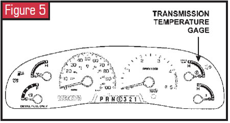
Added to the instrument cluster is a transmission temperature gauge that we think is long overdue. Another new feature on this unit is called the tow/haul mode, which is designed to assist the driver when towing a trailer or a heavy load. All transmission gear ranges, including all five forward gears, are available when using the tow/haul feature.
The new transmission also uses a new fluid called Mercon® SP, which is not interchangeable with Mercon® or Mercon® V. The use of any fluid other than Mercon SP can result in abnormal operation and/or transmission failure. Ford recommends replacing the fluid and bottom-pan filter every 48,000 km (30,000 miles) regardless of normal or special operating conditions.
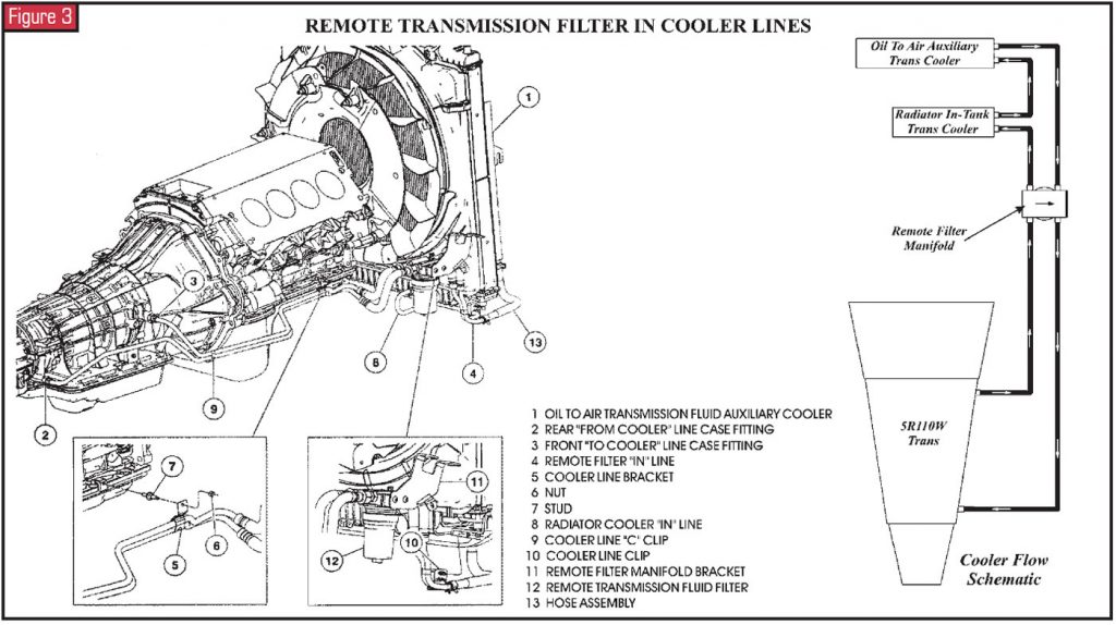
This transmission also is equipped with a new remote fluid filter. This filter passes 10% of the fluid through a small orifice into a serviceable screw-on filter element. The filtered fluid then is directed back into the rear lube circuit through the large opening in the remote-filter manifold. The remote filter in the cooler lines also should be replaced at each service interval. This unit is equipped with an oil-to-air (OTA) cooler in front of the radiator. Ford recommends replacing the OTA cooler as part of any overhaul or exchange. Do not try to back-flush and clean the OTA cooler.
General Description and Operation
The TorqShift transmission has seven range positions that can be selected with the manual shift lever: P, R, N, (D), 3, 2, 1. A description of each range follows.
- P – In Park, there is no power flow through the transmission. The parking pawl is engaged, locking the output shaft to the transmission case. The engine can be started and the ignition key can be removed.
- R – In Reverse, the vehicle can be operated in a rearward direction at a reduced gear ratio.
- N – In Neutral, there is no power flow through the transmission. The output shaft is free to turn, and the engine can be started. This position can also be selected while vehicle is moving, to restart the engine if that becomes necessary.
- (D) – The Overdrive position is the normal position for most forward-gear operations. It provides automatic upshifts and downshifts, apply and release of the converter clutch, and maximum fuel economy during normal operation.
- 3 – This position provides third-gear start and hold, for improved traction on slippery roads. It also can be selected at any vehicle speed for improved engine braking. The transmission will not downshift if it would cause an engine-overspeed condition.
- 2 – This position provides second-gear start and hold, for improved traction on slippery roads. It also can be selected at any vehicle speed for improved engine braking. If this position is selected at higher speeds, the transmission will downshift to the next-lower gear and will downshift into second gear after the vehicle decelerates to a speed that will not create an engine-overspeed condition.
- 1 – Manual low gear provides 1st-gear operation only. This position also can be selected at any vehicle speed to provide improved engine braking for descending steep grades. If this position is selected at higher speeds, the transmission will downshift to the next-lower gear and will downshift into first gear after the vehicle decelerates to a speed that will not create an engine-overspeed condition.
Battery Disconnect, Dead Battery
Any time the battery is disconnected for any reason, a new PCM has been installed or the calibration has been re-flashed, the adaptive strategy for the “Engagement Schedule” must be updated.
The following procedure will prevent the customer from returning with complaints of firm or harsh engagement.
Note: All the following engagements must be performed for engagement pressures to adapt correctly with the new calibration.
- Install diagnostic equipment and monitor TFT.
- Warm the transmission fluid to 54°C (130°F) as
indicated by the TFT. - Perform five engagements from Park to Reverse, each five seconds apart.
- Perform five engagements from Drive to Reverse, each five seconds apart.
- Perform five engagements from Reverse to Drive, each five seconds apart.
- Perform five engagements from Neutral to Drive, each five seconds apart.
Description and Operation of Electrical Components
Here is a brief description of each of the sensors and actuators used by the PCM for proper transmission operation:
Powertrain Control Module (PCM)
The Powertrain Control Module (PCM) controls the operation of the transmission. Many input sensors provide information to the PCM, which then uses this information to control actuators that determine transmission operation.
Engine Coolant Temperature Sensor
This sensor is a thermistor in which resistance changes when the temperature changes. The resistance of the sensor increases as engine temperature decreases, and the voltage sent to the PCM increases. The PCM uses this information to help determine TCC operation.
Intake Air Temperature Sensor
This sensor also is a thermistor in which the resistance changes with temperature. The resistance decreases as the intake air temperature increases. The IAT provides air-temperature information to the PCM, which uses it to help determine transmission line pressure and shift scheduling.
Accelerator Pedal Position Sensor
This sensor is mounted on the accelerator pedal on 6.0-liter diesel applications. The APP sensor detects the position of the accelerator pedal and sends this information as a voltage to the PCM. The PCM uses APP-sensor information to help determine line pressure, shift scheduling and TCC operation.
Failure of the APP sensor will cause the transmission to operate at a higher-than-normal line pressure to help avoid damage. This will result in harsh upshifts and harsh engagements.
Brake Pedal Position Switch
This switch supplies battery voltage to the PCM to indicate that the brake pedal is applied. The PCM uses this information to release the torque-converter clutch, speed control and auxiliary idle (if the vehicle is so equipped).
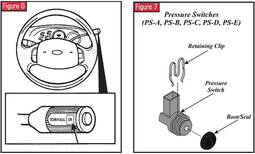
Tow/Haul Switch
This switch on the end of the manual shift lever is a momentary-contact switch. It provides a signal to the PCM when pressed by the operator, resulting in a change in shift and TCC scheduling. When the tow/haul switch has been pressed, the indicator lamp at the end of the manual shift lever will illuminate “Tow/Haul – ON.” Pressing the switch again cancels tow/haul and turns off the TCIL.
Transmission Control Indicator Lamp
With the tow/haul switch on, the indicator lamp at the end of the manual shift lever will illuminate “Tow/Haul – ON.” When tow/haul is activated, upshifts occur at a higher vehicle speed, and during deceleration, downshifts also occur at a higher vehicle speed, providing added engine braking. Pressing the switch again cancels tow/haul and turns off the transmission control indicator lamp (TCIL). The PCM controls the operation of the TCIL. The PCM also may flash the TCIL on and off to alert the driver that a transmission operational error has occurred when it detects certain faults in monitored sensors, solenoids or other transmission components.
4X4 Low Switch
The 4X4 Low Switch, on the instrument panel to the driver’s right, sends a ground signal to the instrument cluster when the vehicle is in 4X4 Low. The PCM then receives 4X4 Low status from the instrument cluster and adjusts the transmission shift schedule accordingly. Four-wheel “High” can be selected at any vehicle speed up to 55 mph.
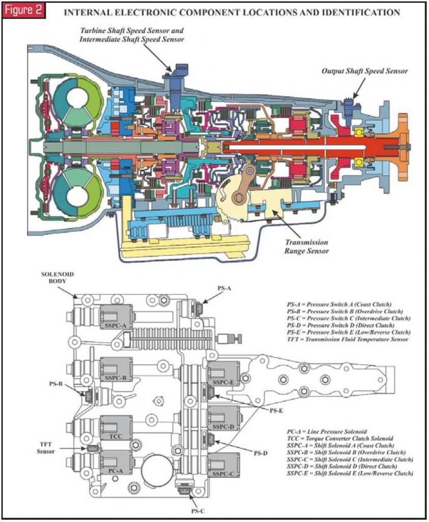
Transmission Solenoid-Body Assembly
The solenoid body assembly is bolted to the transmission case inside the bottom pan and looks similar to what we have previously referred to as a valve body. It contains the following:
- Seven variable-force solenoids
- Five normally closed pressure switches
- Transmission-fluid temperature sensor
- Manual shift valve
- Overpressurization relief ball.
There is a solenoid and a pressure switch dedicated to the function of each clutch pack, except the forward clutch, as it is controlled by the manual valve. There are no other valves in the solenoid body except for the pressure-relief ball and spring.
The different-design solenoids are keyed differently to prevent misassembly in the solenoid body, and all are retained with a large “E” clip. The “natural”-colored wire connectors connect to the solenoids. The black connectors connect to the pressure switches. There are separate connectors for the TFT sensor and for the TR-P sensor. All of the solenoids except the line-pressure solenoid can be serviced without removing the solenoid body from the case.
Line-Pressure-Control Solenoid
The line-pressure-control solenoid (PC-A) is an inversely proportional three-port solenoid. The pressure output is inversely proportional to the applied DC current supplied through an electronically controlled driver. The current is varied between 0 amp and 1 amp from the PCM, and 0 amp equals maximum pressure in the oil circuit. The PC-A solenoid controls the line-pressure oil circuits.
Torque-Converter-Clutch Solenoid
The torque-converter-clutch (TCC) solenoid is a directly proportional three-port solenoid. The pressure output is directly proportional to the applied DC current supplied through an electronically controlled driver. The current is varied between 0 amp and 1 amp from the PCM, and 1 amp equals maximum pressure in the oil circuit. The TCC solenoid controls the apply and release rates of the converter clutch.
Shift-Solenoid Pressure-Control Solenoids
The overdrive (SSPC-B), intermediate (SSPC-C) and low/reverse (SSPC-E) clutches are each controlled by a directly proportional three-port solenoid. The pressure output is directly proportional to the applied DC current supplied through an electronically controlled driver. The current is varied between 0 amp and 1 amp from the PCM, and 1 amp equals maximum pressure in the particular clutch oil circuit. The shift solenoid controls the apply and release rates of the particular clutch pack.
The coast (SSPC-A) and direct (SSPC-D) clutch packs are each controlled by an inversely proportional three-port solenoid. The pressure output is inversely proportional to the applied DC current supplied through an electronically controlled driver. The current is varied between 0 amp and 1 amp from the PCM, and 0 amp equals maximum pressure in the particular clutch oil circuit. The shift solenoid controls the apply and release rates of the particular clutch pack.
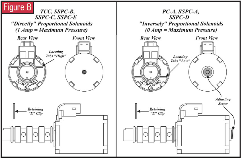
Pressure Switches
Each of the five shift-pressure control solenoids has a corresponding pressure switch, which is normally closed. The pressure switch is designed to open when shift-solenoid control pressure exceeds 40 psi. All five of the pressure switches are identical and will interchange in the solenoid body. Their particular functions follow:
- PS-A = Coast clutch
- PS-B = Overdrive clutch
- PS-C = Intermediate clutch
- PS-D = Direct clutch
- PS-E = Low/Reverse clutch
Turbine-Shaft-Speed and Intermediate-Shaft-Speed Sensors
The turbine-shaft-speed (TSS) and intermediate-shaft-speed (ISS) sensors are Hall-effect sensors requiring a 12-volt power supply and a ground. In this unit both sensors are incorporated into one housing. The other two terminals at the sensor are for TSS and ISS signals to the PCM. The sensor detects teeth on the coast-clutch input hub for TSS signal, and the adjacent overdrive ring-gear teeth for the ISS signal. Both sensors read 30 teeth per revolution. The TSS/ISS sensors are mounted externally on the transmission case. The TSS/ISS sensors’ input to the PCM is digital and used to determine line pressure, shift timing and TCC operation.
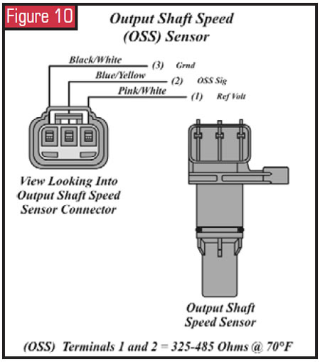
Output-Shaft-Speed Sensor
The transmission output-shaft-speed (OSS) sensor is on the extension housing. The OSS is a Hall-effect sensor. The OSS reads a set of gear teeth on the park gear that are different from the teeth used for the park function. The OSS signal to the PCM is used for vehicle-speed signal, shift scheduling and TCC operation. The OSS has bi-directional capability and uses a digital output.
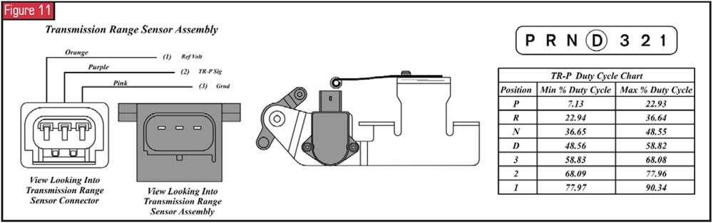
Transmission Range Sensor Assembly
The transmission-range (TR-P) sensor assembly is an internally mounted sensor that includes the detent spring, rooster-comb lever and bracket, next to the solenoid body and bolted to the transmission case. The transmission-range sensor is non-adjustable and is not serviced independently. The TR-P sensor contains electronic circuitry that provides the PCM a fixed frequency, at a duty cycle, for each of the seven positions of the manual shift lever. The PCM uses the TR-P sensor signal for starting in Park and Neutral only, reverse-lamp operation, and for line-pressure control, shift scheduling and TCC operation.
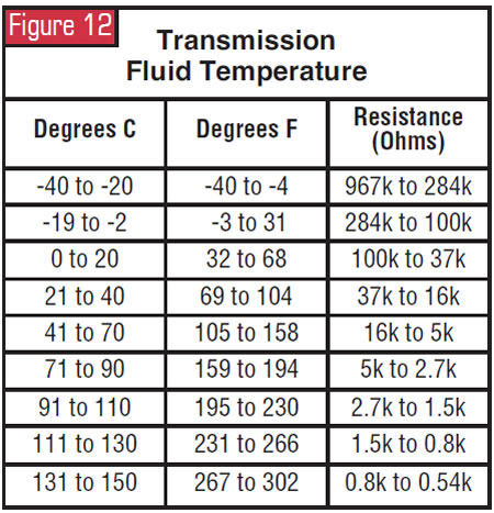
Transmission-Fluid-Temperature Sensor
The TFT sensor twist-locks into the solenoid body and is a temperature-sensitive device called a thermistor. As the fluid temperature increases, the TFT resistance decreases. The PCM uses the TFT signal as an input to determine cold- and hot-temperature shift scheduling and for TCC apply and release scheduling.


