Premature Failure of Mitsubishi Galant Ring Gears - Transmission Digest

Premature Failure of Mitsubishi Galant Ring Gears

Torque-converter rebuilders have been reporting an increase in the number of failed ring gears on Mitsubishi Galant converters. Most of the failed ring gears are found on 2006-08 vehicles equipped with V-6 engines, and the failures seem to occur soon after the vehicle’s starter has been replaced.

Premature Failure of Mitsubishi Galant Ring Gears

Torque Converter Tech Tips

Subject: Failure of starter ring gear
Vehicle Application: 2006-08 Mitsubishi Galant V-6
Essential Reading: Rebuilder, Diagnostician
Author: Ed Lee

Torque Converter Tech Tips

  • Subject: Failure of starter ring gear
  • Vehicle Application: 2006-08 Mitsubishi Galant V-6
  • Essential Reading: Rebuilder, Diagnostician
  • Author: Ed Lee

Torque-converter rebuilders have been reporting an increase in the number of failed ring gears on Mitsubishi Galant converters. Most of the failed ring gears are found on 2006-08 vehicles equipped with V-6 engines, and the failures seem to occur soon after the vehicle’s starter has been replaced.

Prior to the ring-gear failures, most customers report hearing a noise during startup followed by a condition of starter non-engagement. In most vehicles, the starter ring gear is on the outer diameter of the flex plate; when a ring gear fails, the flex plate must be replaced. On most Mitsubishi Galants, the ring gear is mounted directly on the converter, which makes it more difficult and much more expensive to replace. If the mileage of the vehicle or the appearance of the ATF makes the condition of the transmission questionable, replacing the converter and overhauling the transmission may be a better option than simply replacing the converter. If it is a low-mileage vehicle and the ATF appears to be in good condition, it is possible to replace only the ring gear.

Unfortunately, the location of the ring gear on the Galant converters makes it impossible to replace the gear without disassembling the converter. The welds used to secure the ring gear to the cover are too close to the TCC reacting surface to allow the ring gear to be replaced with the converter still assembled.

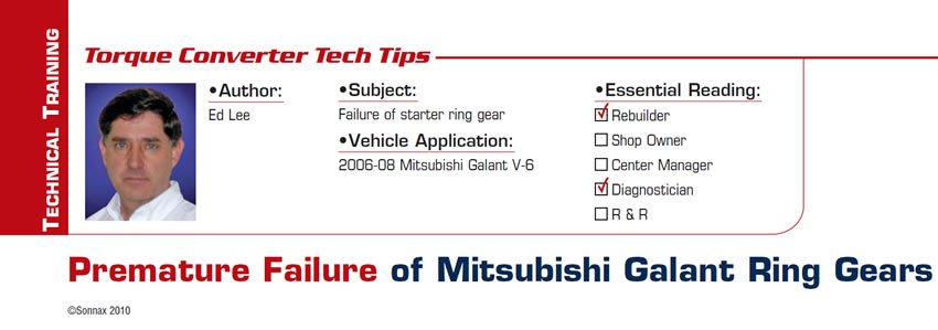
A ring gear typically can be removed from the converter by machining the welds off on a lathe. On some models of the Galant the ring gear is attached to the outer diameter of the converter cover. On the 2006-08 Galant, the ring gear is mounted to the front of the cover directly adjacent to the four mounting pads. The proximity of the ring gear to the mounting pads makes ring-gear removal more difficult. On those converters, a milling machine is a better option than machining the welds off on a lathe. If you are removing only one ring gear, you can secure the cover directly to the bed of the milling machine (Figure 1).

If you are removing more than one ring gear, you may want to mount your cover to a turntable. To remove the weld, plunge into the weld until the milling bit contacts the ring gear (the ring gear is harder than the weld and has a different feel on the cross feed). Do not force the milling bit into the ring gear. If you do, the bit will quickly become dull.

Why did the OEM ring gear fail?

Although the cause of the ring-gear damage is not totally clear, all known failures have been in vehicles with aftermarket replacement starters. The OEM replacement starter costs about $160, so customers often elect to go with an aftermarket starter that is about $40 less. In the short run, these customers did save $40, but in the long run they also had to pay for the R&R of the converter and the cost of the replacement converter and opted to go back to the OEM replacement starters to prevent repeat failures.

Ed Lee is a Sonnax Technical Specialist who writes on issues of interest to torque converter rebuilders. Sonnax supports the Torque Converter Rebuilders Association. Learn more about the group at www.tcraonline.com.

©Sonnax2010

You May Also Like

Sherlock Holmes Approach to an AB60 No-Move Situation

The effectiveness in diagnosing automatic transmission malfunctions is an art form. Although there are similarities among the wide varieties of transmissions on the road, each transmission has its own peculiarities. Aside from having mechanical, hydraulic, and electrical hardware systems to contend with, software/programming issues and various vehicle platforms make diagnostics much more difficult.  Using scopes provides

ab60

The effectiveness in diagnosing automatic transmission malfunctions is an art form. Although there are similarities among the wide varieties of transmissions on the road, each transmission has its own peculiarities. Aside from having mechanical, hydraulic, and electrical hardware systems to contend with, software/programming issues and various vehicle platforms make diagnostics much more difficult. 

GM 6T40 Pump Identification Guide

The 6T40 was introduced in 2008 for General Motors front-wheel-drive cars in the Chevrolet Malibu and has gone through several changes throughout its three generations, specifically in the pump area. The 6T40 is closely related to the more lightweight 6T30 and the heavier duty 6T45 and 6T50. Generation one started phasing out during the 2012

Seeing the Forest AND the Trees

They say that the proverbial phrase “I couldn’t see the forest for the trees” means that a person or organization cannot see the big picture because it focuses too much on the details. Related Articles – 4L60E Harsh 1-2 Shift – TASC Force Tips: Diagnosing 8L45 & 8L90 Shift Complaints – TASC Force Tips: Hydraulics

The Manifold Pipeway

The Honda six-speed transmission has been on the bench of many specialty shops for one reason or another (figure 1). But, for those of you who have yet to lay your hands on one, mounted on the upper side of the unit is one of the largest, if not the largest solenoid and pressure switch

8L90 Vacuum Testing

Below are the diagrams for vacuum testing GM 8L90 transmissions. Note: OE valves are shown in rest position and should be tested in rest position unless otherwise indicated. Test locations are pointed to with an arrow. Springs are not shown for visual clarity. A low vacuum reading indicates wear. For specific vacuum test information, refer

Other Posts

Critical Wear Areas & Vacuum Test Locations for FORD 6R80/6R100

Note: OE valves are shown in rest position and should be tested in rest position unless otherwise indicated. Test locations are noted with an arrow. Springs are not shown for visual clarity. Low vacuum reading indicates wear. For specific vacuum test information, visit www.sonnax.com. Related Articles – Hydraulics Fundamentals: Shift & Relay Valves – Another

Hydraulics Fundamentals: Shift & Relay Valves

Shift valves and relay valves share a lot of the same duties. This article is one of a series by Sonnax exploring how valves and hydraulic circuits work and what results when they quit functioning correctly.

Another 62TE ‘No-Move’ Possibility

Most seasoned techs have several quick diagnostic steps they take when faced with a transmission malfunction. The type of problem and transmission determines which steps to take. For example, a “no-move” condition. Related Articles – Ford 8F24 mechanical diode failure – Ford 8F35 maintenance tips: Planetary failure and no-pressure conditions – Don’t fear customer complaints about

Hydraulics Fundamentals: Clutch Regulator Valves

Knowing how these circuits work and the slightly different variations that the manufacturers utilize should pinpoint any valve body-related issues