Up To Standards
- Author: Mike Weinberg
- Subject Matter: Tools and techniques of ring and pinion setup
There are many ways in which I choose topics for my column. Sometimes it is to introduce new technology, and other times it reflects the number of calls on our tech line that illustrates the need to enlighten guys in the field regarding specific procedures for repairs. This article will attempt to explain once again the proper procedures to successfully replace a ring-and-pinion set. Although I have addressed this topic more frequently than I want to, ring-and-pinion setup continues to mystify many technicians. Replacing a ring-and-pinion set is one of the simplest and most profitable repairs for a shop. There has always been a mystique involving what should be an easy repair and in the past many shops turned away this work or farmed it out to a specialist. Perhaps there are many new people coming into the business, or shops that are not that experienced are trying to add more services for their customers to increase gross sales, or more customers are looking to improve fuel economy or vehicle performance; whatever, this simple repair generates more tech calls than virtually anything else. Hence, we go over procedures to follow for a simple, cost effective repair.
There are some special tools that are necessary for an easy ring-and-pinion replacement, and there are some special tools that can be purchased to really make short work out of this job. Basic tools necessary beyond simple hand tools are an accurate dial indicator, a direct-reading micrometer and Vernier caliper, a quality set of bearing pullers, a case spreader for some types of rears, a breaker bar that can bolt to the pinion yoke to hold it steady to crush the sleeve on the pinion to the required depth, and an understanding as to what is needed to achieve a quality rebuild.
Special tools well worth the investment are a good set of “bucket” bearing pullers as you may have to remove a new bearing to reset pinion-depth shims or carrier-side shims. The investment in these tools will pay off rapidly as you will have to replace fewer new bearings due to cage damage or other problems when the puller slips. Another tool that makes short work out of this job you can make yourself, and that is a set of “setup bearings.” There are not that many sizes of pinion and carrier bearings for most rears. Start by buying two extra carrier bearings and one each on inner and outer pinion bearings for the job you are doing. Take one set of new bearings and using a brake hone to remove material from the inner-bearing bore until the interference fit is gone and the bearing will slide on and off by hand. Mark the bearings and use them for setting up the rear so that swapping shims becomes a 10-second job. Then once your setup is perfect, remove the setup bearings and replace them with the other set of new bearings and you will never damage a bearing pulling it again – cheap and fool-proof method of setting pinion depth and backlash to the required specs.
For shops that do some oddball work, investing in a pinion-depth gauge set will allow you to measure pinion depth precisely with no effort. Remember the basics of ring-and-pinion repair is setting the depth of the pinion into the ring gear and moving the carrier side to side to establish correct backlash and gear pattern on the ring gear.
We live in a global economy and the parts we are working with, OEM or aftermarket, are being sourced all over the world. On most pinion gears will be found a head stamp that will have a fractional number, plus or minus. This is meant to tell you what deviation from the original gear is present during the manufacture of the replacement gear. The problem that arises here is that the number can be USA standard or metric, and a wrong assumption here will make a lot more work for you. Ask your supplier what the head stamp is (USA or metric) to be sure of the correct shim selection. Some gears will have no head stamp as the manufacture quality is so good, there is no deviation. If that is the case, reuse the original pinion shim, which will be correct most of the time. If you use slip-fit setup bearings, changing shims is a breeze.

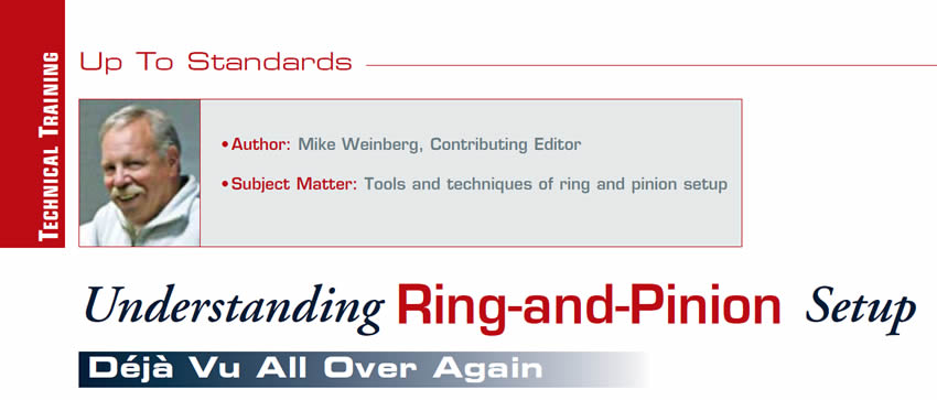
The next step is understanding backlash and gear patterns. To get to the correct backlash dimension you must know what type manufacture process for ring and pinion you have. There are two types of gear train, face-milled and face-hobbed. This goes to the way the gear set was cut during the manufacturing process and how that affects backlash specs, back lash being the travel of the ring gear against the pinion if one of them is held stationary. There are some terms here that need to be understood. The “toe” of the gear will be closest to the center of the axle line. The “heel” of the gear will be toward the outside diameter of the ring gear. To find out what manufacture was used in the gear it is only necessary to look at the top land of any tooth on the ring gear. On a face-hobbed gear, the top land will be equal in width from heel to toe. On a face-milled gear the top land will be wider on the heel of the tooth and get narrower at the toe.
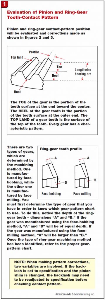
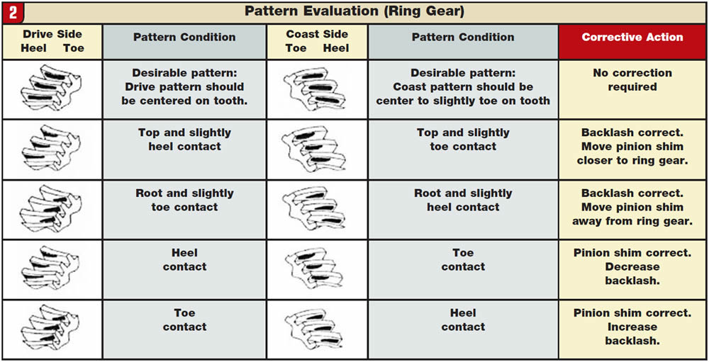
On a face-hobbed gear the backlash spec will usually run between 4-6 thousandths of an inch. On a face milled gear backlash will usually run between 8-10 thousandths of an inch, and sometimes bigger on larger trucks. Once you have established the correct backlash, it is time to run a contact pattern on the gears. After rotating the gear set by hand in both directions 5-10 times, paint up the ring gear with a marking compound included in the ring and pinion set and review the pattern made as the gears mesh. I have included two charts here to help you understand and adjust the pattern and backlash. Whether face-milled or face-hobbed gears are used, a correct pattern will be centered on the gear between the heel and the toe and between the top land of the gear and the root of the tooth. No marking compound to be had, buy a tube of white zinc oxide at the drug store, which will work perfectly. When marking up the gears, a little compound goes a long way.
Most pinion gears will have a crush collar or sleeve that is meant to set the drag or torque necessary to turn the pinion against the pinion bearings. It takes considerable torque to crush that collar to the proper depth. The pinion nut and washer are built to lock into place so they don’t back off. Always grease the pinion threads and the washer before attempting to crush the collar, so that friction does not add to the torque necessary for the job. A long breaker bar followed by a 250 lb.-ft. torque wrench will get the job done, please no air tools. If you crush the collar too much, it must be replaced with a new one. While I am at it, please remember to mark the carrier bearing caps when taking apart the rear, so they go back as they were disassembled. With a prick punch or die grinder, put one dot on both cap and housing so you know which side it goes back on. Match the dot to the cap on the housing.
Make sure that you fill the rear with the correct lube, to manufacturer specs. There are some gears and limited-slip differentials that will work better with mineral oil than synthetics. Make sure you get the correct oil into the rear. New ring-and-pinion sets require a proper break in procedure. Never let the customer put the car on a chassis dyno right after the repair as it will fail the gear set. Proper break-in procedure requires several road tests. The gears were precision lapped during manufacture, but they need to break in due to deflection of the ring gear with the full vehicle weight and torque, and excess heat generated by new parts mating in the real world environment. Drive the vehicle at LIGHT throttle for 15-20 miles. Park it and let the gear train cool down. Drive it again at LIGHT AND MEDIUM throttle for 15-20 miles. Let it cool down and then deliver the car. Instruct the customer not to do any towing for the first 500 miles of use, which also includes racing. Have the customer return to the shop at 500 miles for a fluid change, which will get rid of any metallic debris created during the break-in period and prevent gear or bearing premature wear. If you understand the dimensional spacing and how it affects the gear set, it is not hard. If you don’t have an understanding of the job at hand it becomes very hard. I’d really like to not write this article again. If you go to the Transmission Digest website you can look up and download other articles written on this subject.
Mike Weinberg is president of Rockland Standard Gear.