
TASC Force Tips
- Author: Ed Lee
Adjusting Clutch Clearance
Unless you have the ability to machine the apply piston, adjusting clutch clearance in a 4L30 E transmission has been a difficult task. When you’re adjusting clearance on the second-clutch drum, it is helpful to know that the THM200 forward- and direct-clutch friction plates are the same dimensions as those of the 4L30 E second clutch but are 0.015 inch thinner. Installing the thinner clutches will allow you to add a clutch for extra holding power or make adjusting proper clearance much easier.
Adjusting the third or direct clutch has presented similar problems. In 1998, the need for more holding power in the direct clutch resulted in the addition of more clutches that were thinner. The new clutches were 0.063 inch thick, more than 0.025 inch thinner than the originals. Until recently, the clutches (p/n 96017371) were available only from the dealer. The cost of more than $8 each made them a less-desirable way of adjusting clutch endplay. Alto now makes a replacement clutch at a fraction of the cost. Its part number for this clutch is 038700-1.6.
The overdrive clutch has two friction plates. Between the two frictions are two steel plates back to back. You will want to check the overdrive-clutch clearance carefully. In many instances, there is enough room for an extra friction to fit between the two middle steels and still allow sufficient clutch clearance.
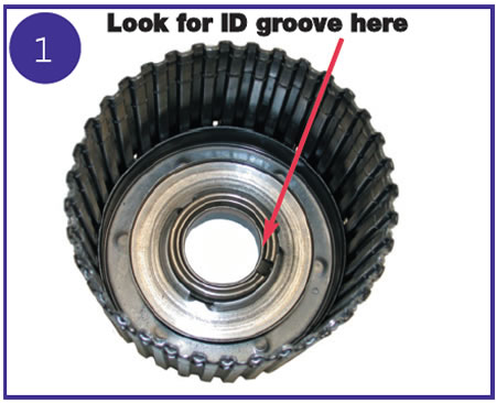
The direct-clutch drum, piston and one-way clutch/pressure plate were changed when the extra clutches were added. There are a few things that you need to know about these changes and how they affect other parts. The snap-ring groove that retains the second-clutch return spring was lowered by 0.070 inch to clear the new dished direct-clutch drum. The surfaces that affect endplay were not changed, so you will not find this problem with an endplay check. You must identify the new second-gear drum by the identifying ring on the thrust-washer surface (see Figure 1). The new-design second-gear drum can be used with the early or late direct drum. But the early-model second-gear drum will interfere with the late-model direct drum.
The bottom of the new direct-clutch piston is dished to mate with the new drum. The new dished piston will fit both the early and new direct drums, but the early flat piston will not fit the new drum. The pressure plate/one-way clutch in the direct-clutch drum also was changed. The surface that meets the clutch pack was machined so that a friction clutch could contact this surface. The earlier pressure plate/one-way clutch did not have a machined clutch surface. As with the direct drum and piston, the late-style pressure plate will fit the early drum, but you cannot put the early-style pressure plate into the late-style drum, because there is no machined surface for the friction clutch to ride against.
No Overdrive, or Slipping in Overdrive, After Overhaul
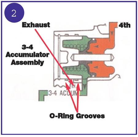
There are two very good reasons for not replacing the aluminum fourth-clutch accumulator cap with the formed-rubber replacement cap. First, the inner O-ring for the aluminum cap does not contact the formed-rubber cap. This allows 3-4 accumulator oil to leak from the exhaust passage that normally is sealed off by the O-ring. Second, the formed-rubber replacement cap is 0.450 inch shorter than the aluminum cap. Since the aluminum cap is the stop for the fourth-clutch accumulator piston on the early-model transmission, substituting the aluminum cap with the formed-rubber end cap will allow the fourth-clutch accumulator piston to overtravel. This will exhaust fourth-clutch oil into the 3-4 accumulator passage, which is already open to exhaust because of the bypassed inner O-ring (Figure 2).
Broken Plastic Thrust Washers
There are two plastic thrust washers in the 4L30 E transmission, and more often than not you will find one or both of them broken. You may replace the broken thrust washers with new ones and hope that they don’t break again before your warranty runs out. Another idea is to replace the thrust washer with a thrust bearing.
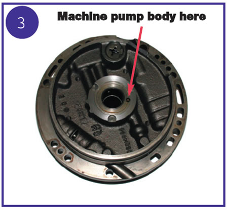
You can replace the front thrust washer with the bearing that is normally between the reaction sun gear and rear internal gear in a 440 T4 transmission. Check your endplay. The original thrust washer normally measures 0.080-0.090 inch. The thrust bearing measures 0.130 inch. Machine the difference between the original thrust washer and the thrust bearing from the back of the oil-pump body (see Figure 3). Leave a step to center the inner diameter of the bearing. This bearing has a large-enough I.D. for clearance on the lube orifice.
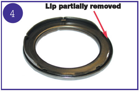
You also can replace the thrust washer between the center support and the second-clutch drum with a thrust bearing. The bearing that works well in this position is in either the E4OD (on top of the input planet) or the AXOD/AXOD-E transmission between the driven-sprocket support and the intermediate/direct drum. One race of this bearing has an outer lip that must be removed (see Figure 4). Check your endplay. This thrust washer usually falls into the range of 0.080-0.090 inch. Now machine the difference between the thrust washer and the bearing off the center support and the second-gear drum. Remove 0.030 inch from the center support and the remaining 0.020-0.030 inch from the second-gear drum. Machining 0.030 inch from the center support leaves sufficient material for the snap ring that holds the reverse piston-spring retainer and puts the bearing in good position for the lube orifice.
Leaks (Center Support to Main Case)
The wiring harness passes through two passageways between the center support and the main housing. These passageways are sealed with O-rings. Sometimes the compression on these O-rings is not sufficient to prevent leaks. The O-ring for the Rodeo 4×4 speedometer housing has the same outside diameter but is 0.020 inch thicker than the original O-rings. This provides a much better seal. You can find one such O-ring in one of the sub-packs of most 4L30 E gasket sets.
Code 26
In 1993 the description for Code 26 was “2-3 shift solenoid circuit (signal voltage low).” In 1994 the description for Code 26 was “supply voltage circuit (supply voltage high).” This change makes about as much sense as changing the meanings of words so people will buy new dictionaries. Fortunately, Code 26 has stayed the same through the rest of its history. If you are not sure about your Code 26, watch your voltmeter with the vehicle in park as you bring engine speed up to 3,500-3,800 rpm for about 25-30 seconds. If the voltage regulator is bad, it will max out the voltmeter (sometimes as much as 19 volts).
There is a safety recall for the defective voltage regulators (this translates to free replacement). You can find the recall under Honda service bulletin 97-026. The defective regulators are on ’94-’97 Passports and ’93-’97 Rodeos. The summation of the bulletin is that a large number of these voltage regulators were defective. If the regulator has been replaced, the new regulator plug receptacle will have a yellow paint mark on it. If the recall has been done, there also will be a “campaign completed” sticker affixed to the driver-side doorframe, directly below the manufacturer’s identification label. If the recall has not been done, make sure that it gets done.
Code 65-66 (1993)
Code 15-16 (1994-Up)
Mystery Oil-Temperature Sensor
Locating the oil-temperature sensor often is more difficult than troubleshooting it. The oil-temperature sensor in a 4L30 E is inside the convoluted tubing that runs next to the main valve body, immediately before the two shift solenoids. If you have determined that the temperature sensor is defective and must be replaced, replacing the entire interior wiring harness is the best option. I hope you have retained at least some of your sanity.

The TASC Force (Technical Automotive Specialties Committee) is a group of recognized industry technical specialists, transmission rebuilders and Sonnax Industries Inc. technicians.


