Technically Speaking
- Subject: No upshifts from first gear after rebuild; reverse OK
- Unit: 4L30-E
- Vehicle Applications: Isuzu Trooper and Rodeo
- Essential Reading: Rebuilder, Diagnostician, R & R
- Author: Wayne Colonna, ATSG, Transmission Digest Technical Editor
In the world of transmission diagnostics, from time to time there is a scenario in which the diagnostics performed ends up being a waste of time. In some situations it can be partially attributed to the “out of sight, out of mind” syndrome, as is the case with a 4L30-E transmission in Isuzu Trooper and Rodeo vehicles. The problem occurs mostly after the transmission has been re-installed.
Afterward the complaint is first and reverse gear only with no upshifts, yet there is a vehicle-speed signal and there are no codes.
When this system defaults to limp mode, the transmission will have fourth-gear starts in the “D4” position. Since the transmission is taking off in first gear it means that the system did not initiate the failsafe feature. So what most transmission technicians do under these circumstances is to replace the mode-select switch (neutral-safety switch). And shooting from the hip, it is a pretty good guess, but ultimately it ends up being a waste of time.
What is misleading is that with the instrument cluster indicating a vehicle speed and no diagnostic codes being stored, an output-speed signal is no longer considered a possible cause of the problem. But once the technician learns that the vehicle-speed signal displayed on the dash is not the signal used to upshift the transmission, diagnostic time begins to lead to the solution.
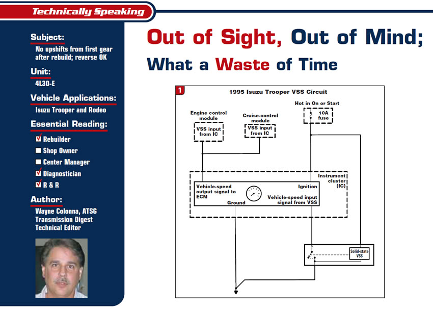
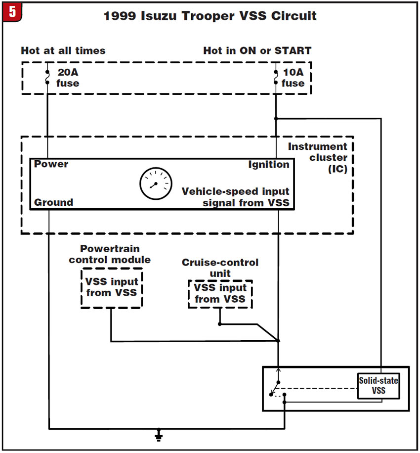
Figure 1 is a wire diagram for a vehicle-speed sensor (VSS) in a 1995 Isuzu Trooper. From this wire diagram you can see that the speed sensor is a three-wire solid-state sensor that sends a speed signal directly into the instrument cluster. The instrument cluster then sends this signal to the engine control module (ECM) and cruise-control module (CCM). Now, isn’t this interesting? What about the transmission control module (TCM)? Where does it get its vehicle-speed signal?
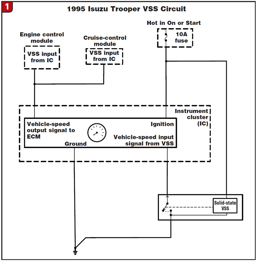
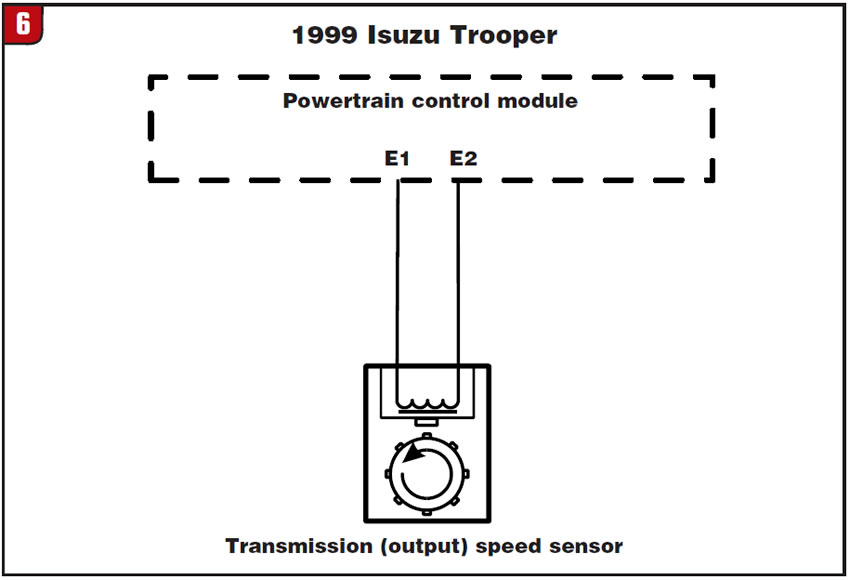
Figure 2 is a wire diagram for the “transmission speed sensor” (TSS), a typical two-wire AC pulse generator. It is this sensor that provides an output-shaft-speed signal that the TCM uses for shift scheduling. This sensor is mounted on top of the transmission in an adapter housing between the transmission and extension housing or transfer case.
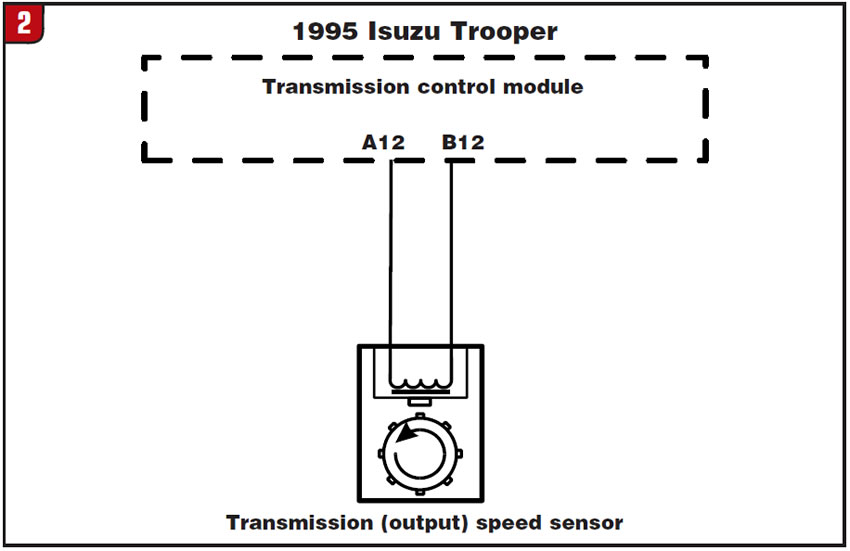
Figure 3 is a view of this TSS (not to be confused with turbine-speed sensor) in a two-wheel-drive application, and Figure 4 shows it in a four-wheel-drive application.
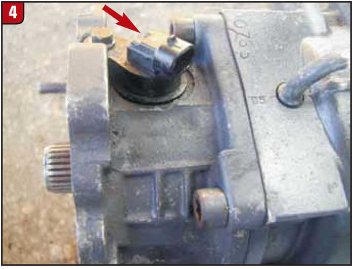
Often, connecting the wiring harness to this sensor gets overlooked during installation of the transmission, and especially so in four-wheel-drive applications. In fact, in a four-wheel-drive vehicle it is impossible to see this sensor once the transmission and transfer case are fully installed. Without this signal, the transmission will not upshift.
Why doesn’t a code set when the TSS signal is missing? There are a couple of reasons for this. One is that there is no strategy in place that compares the VSS and TSS signals. Remember, the VSS signal is sent into the instrument cluster and then to the ECM and CCM; the TSS signal is sent directly into the TCM. So there is no communication between the ECM and TCM regarding these signals.
This becomes more obvious with 1996 and later vehicles, as you can see in figures 5 and 6. With these later vehicles the TCM and ECM no longer are separate. These two modules are now combined into one called the powertrain control module (PCM). Now the VSS and TSS signals are both going into the same module, but they are still not being compared.
Another reason that a disconnected TSS does not usually trigger a code is that the criteria for setting the code often are not met during a road test. According to Isuzu*, for this code to set, the selector lever needs to be in any of the forward drive ranges and driven until the engine exceeds 3,000 rpm for a given period of time while the TSS signal remains at a 0 reading. Since the transmission is not shifting out of first with an unplugged TSS, the vehicle is rarely pushed beyond 3,000 rpm long enough to set a TSS code. As a result, considerable time is wasted trying to fix this problem, and since the TSS is out of sight it is also out of mind.
TSS codes are:
- 1990-1993 – Code 39
- 1994-1995 – Code 11
- 1996 & Up – Code P0722/P0723
VSS codes are:
- 1990-1995 – Code 24
- 1996 & Up – Code P0502
Special Note: Isuzu’s description in the factory manual is confusing. It says the criteria for setting a TSS code are: The TCM reads 0 pulses from the VSS when the engine speed was greater than 3,000 rpm, and the gear-selector mode switch identified D, 3, 2 or Low.
What is confusing is the term vehicle-speed sensor in this definition, especially since the VSS receives about 12 volts from the instrument cluster and pulses it to ground four times per revolution. Also, the TCM does not receive a VSS signal but rather reads the TSS. The TSS is an AC pulse generator that produces a wave signal. The TCM reads the top of each of the wave signals as a pulse. To make the factory manual read correctly, all that would be necessary would be to change the term vehicle-speed sensor to transmission-speed sensor; better yet, to say that the TCM reads a 0 sine-wave signal from the transmission-speed sensor.


