Technically Speaking
- Author: Wayne Colonna, Technical Editor
Chances are that a Saturn transaxle has or will come into your shop with the typical complaint of a delayed or harsh engagement into reverse when hot because the pressure-regulator-valve bore is worn. This complaint in most instances can be resolved with Saturn’s 1⁄2 valve-body replacement kit for ’93 and later models (part number 21005813 – about $145). Unfortunately, there are no 1⁄2 valve-body replacement kits for 1991 and ’92 models. To remedy this complaint, Saturn would like for you to buy an entire valve body, which lists for about $540 (part number 21002273).
Nonetheless, when the vehicle comes to the shop with this complaint, there are instances in which the transaxle also needs other repairs. Once the transaxle has been rebuilt, installed and road-tested, the problem with reverse has proved to be resolved. But the discovery of a newly developed problem dampens the repair experience. After the vehicle comes to a stop, the transaxle drops out of gear. When the driver depresses the throttle slightly, the transmission engages simultaneously with the increased engine speed, and the vehicle then can drive away just fine.
This complaint is similar to what a low fluid level or a compromised internal-filter seal would cause, yet reverse engages correctly and stays engaged. Line-pressure checks do not point to any of these possibilities either. This makes the 1st-clutch drum suspect. After all, it does have a molded piston, and molded pistons are notorious for looking good and air-checking well yet still giving problems. It is also possible that the molded lip seal was cut slightly during installation, and so the shop decides to take the unit out – only to discover that everything inside looks great. With fingers crossed, the technician installs a new molded piston and re-installs the transmission, and – you guessed it – the neutralizing condition at stops prevails.
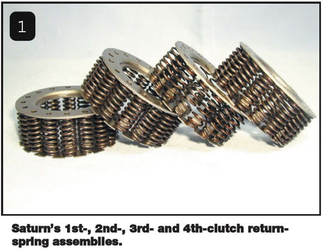
The problem here is in the assembly of the 1st-clutch drum. At first glance, all four of the piston-return-spring assemblies look identical (see Figure 1). Each caged assembly contains 16 springs and has an average overall height of 1.170 inches. The size and configuration of the spring cage allow for these assemblies to be interchanged among drums.
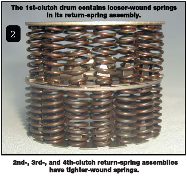
The difference is that the springs inside the assembly for the 1st-clutch drum have a thinner wire diameter and looser coil dimensions than the return-spring assemblies of the 2nd-, 3rd- and 4th-clutch drums (see Figure 2). The return-spring assembly in the 1st-clutch drum has a wire diameter of about 0.62 inch and about eight coils. Each return-spring assembly in the other clutch drums has a wire diameter of about 0.72 inch and about nine coils.
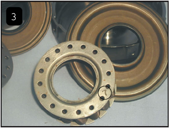
The problem occurs when a 2nd-, 3rd- or 4th-clutch return-spring assembly is placed into the 1st-clutch drum. The increased spring tension is enough to push the piston off, releasing the 1st clutch during idle conditions. Although a careful look at the springs easily could identify the proper cage assembly for the 1st clutch, some caged assemblies also have markings to indicate their differences, such as the number 7 on the assembly shown in Figure 3.
A previously mentioned common cause of delayed engagement into reverse is a worn pressure-regulator-valve bore in the valve body. Another common cause could be a loosened nut on the transaxle’s mainshaft. The 1st-, 2nd-, 3rd- and 4th-clutch feed oil is routed through the back cover (see Figure 4). Look carefully at Figure 4. 1st-, 2nd- and 3rd-clutch oil is directed toward the left-side tube-and-hub assembly. The tube is a 3rd-clutch feed tube that travels down the mainshaft and is supported by an internal bushing near the end of the tube. This bushing also is used to seal and contain third-clutch pressure as it is directed through side holes in the mainshaft and into the 3rd-clutch drum. The input hub directs the 1st-clutch pressure directly into the 1st-clutch drum from between its two sealing rings, and 2nd clutch oil is fed from the top of the hub. This is where it gets interesting.
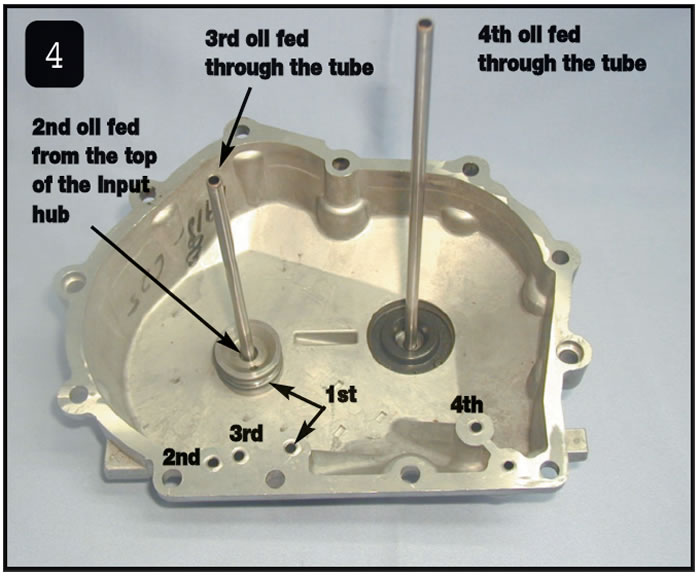
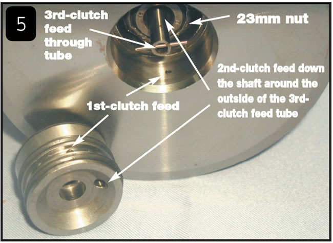
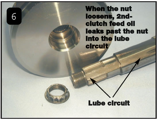
Figure 5 is a view of the 1st-clutch drum fastened to the mainshaft by the 23mm 12-point nut. This is where the tube and hub are positioned in the mainshaft and 1st-clutch drum when the cover is bolted onto the case. For illustration purposes, in Figure 5 the hub and tube have been removed from the cover and the 3rd-clutch tube has been positioned into the mainshaft. The nut not only fastens the 1st-clutch drum to the mainshaft but also seals 2nd-clutch oil. 2nd-clutch oil is fed through the center of the nut down the inside of the mainshaft around the outside of the 3rd-clutch feed tube. This 2nd-clutch oil also is sealed by the bushing in the mainshaft that seals against the 3rd-clutch feed tube. This pressure then is forced through side holes in the mainshaft and into the 2nd-clutch drum. Should the 23mm nut loosen, 2nd-clutch oil is able to get past the back side of the nut and down the flat side of the mainshaft and becomes excellent unintended lube oil (see Figure 6).
And which clutch drum needs to apply along with the reverse fork to make reverse work? You guessed right again – the 2nd clutch. Often the loose mainshaft nut still contains enough pressure to make a good shift from 1st to 2nd, yet the loss of the higher pressure needed for reverse equates to the delayed-engagement complaint.
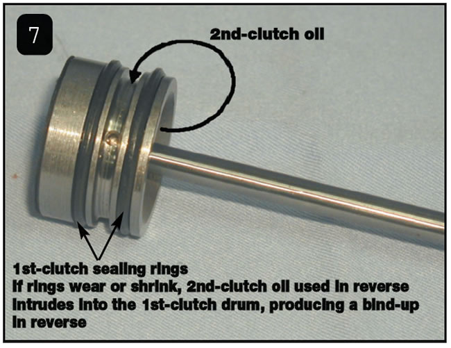
Figure 7 shows another common problem in this area. Should the 1st-clutch-drum rings on the hub shrink, wear or become damaged in any way, when 2nd-gear oil is used in reverse, this pressure can get past the rings and intrude into the 1st-clutch drum. The result is a bind-up or tie-up in reverse, causing this Saturn to be lost in space – excuse me, I meant locked in place.
An additional cause for a bind-up in reverse would be if the 1st drive gear is not fully indexed to all the frictions. Should the bottom one be missed, tightening the nut locks the 1st-clutch drive gear to the drum. This condition will produce the bind-up in reverse and forward movement in neutral. All forward ranges will be fine, as the low sprag will freewheel. Of course, in Park it will want to move forward as well, but with the park/lock gear engaged it will torque down the engine with throttle opening. It is possible to jam up any of the other drive gears in the same manner to produce wrong-gear starts, bind-ups in reverse (with the exception of the 2nd clutch), bind-ups in forward after certain gear shifts have taken place, and creeping forward in neutral.
Build Tip: After the unit is assembled, before bolting up the end cover, place the unit into park. Rotate the input shaft by turning the 1st-clutch housing. The clutch housing should turn freely in both directions. If it turns freely in only one direction, the first drive gear is misassembled and locked to the clutch housing. If it will not turn in either direction, the 2nd, 3rd or 4th drive gear is misassembled.
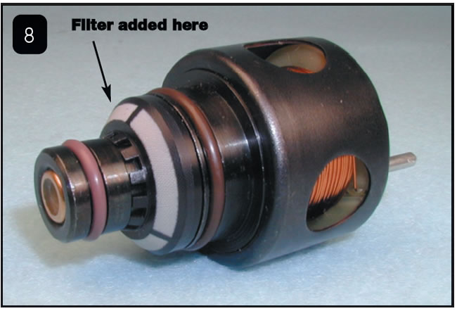
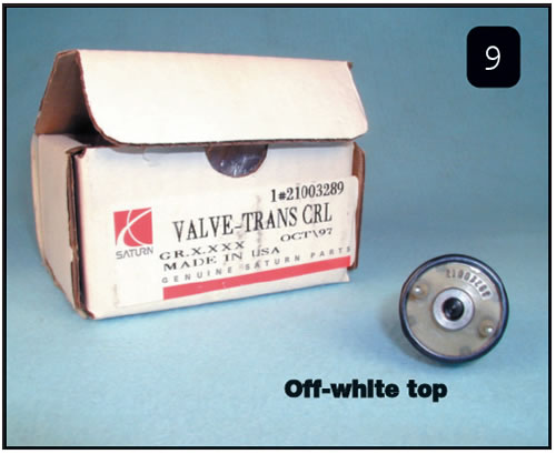
Update Info: Saturn at one time issued a bulletin describing a new-design actuator with an off-white top. The design change involved the addition of a filter on the feed side of the actuator (see Figure 8). Its purpose was to reduce the opportunity for debris to stick the valve inside the actuator. The bulletin went on to say to use this type of actuator in the 2nd/Reverse, 3rd-clutch and 4th-clutch positions. The previous-design actuators with red tops and no screens are to be used in the TCC (torque-converter-clutch) and TFP (transaxle-fluid-pressure) positions. This bulletin no longer is in effect, as the only actuators available for purchase are those with off-white tops and the screens, part # 21003289 (see Figure 9).
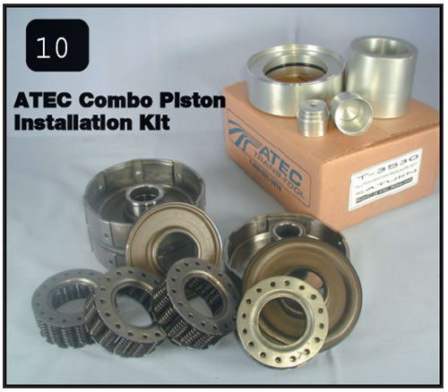
Cutting a seal on one of the molded pistons during assembly is not uncommon. A piston-installation tool now available from ATEC Trans-Tool protects the seals during the installation process (see Figure 10). The tool is designed to accommodate the installation of all four pistons. ATEC’s part number for this tool kit is T-3530.