Up To Standards
- Author: Mike Weinberg, Contributing Editor
One of the most-common repairs performed by transmission and general-repair shops is clutch replacement. The clutch is a high-wear item that must engage and disengage hundreds of times a day. It is subject to a lot of driver abuse; vehicle overloading; wear and failure of linkage, hydraulics and powertrain mounts; and contamination from oil leaks in the engine or transmission.
Most shops understand the basics of quality clutch replacement, which starts with using a quality new clutch set consisting of a pressure plate, clutch disc, release bearing and pilot bearing; replacing or resurfacing the flywheel; adjusting or replacing any worn components, either hydraulic or linkage, that operate the clutch; and resealing any leaking engine or transmission components. What is not commonly understood is the complexity of the design and engineering that go into producing a quality clutch, and this leads to difficulty in diagnosing clutch problems.
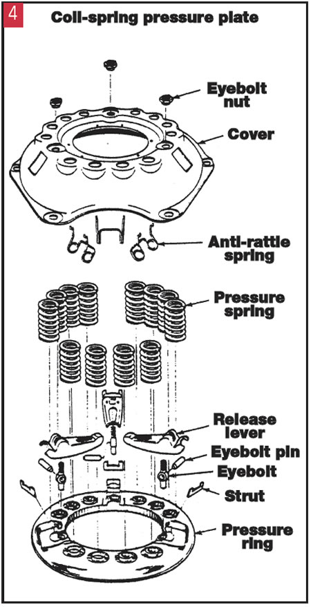
There are two basic pressure-plate designs: coil spring and diaphragm spring. The coil-spring design uses three or four levers to actuate a series of coil springs that provide the clamp load to hold the clutch disc to the flywheel. The diaphragm-spring design uses a slotted Belleville spring to provide the clamp load.
The coil-spring design basically has been discarded for most passenger and light-duty applications because of the high pedal effort associated with that design, space limitations in modern vehicles and cost of manufacture. The diaphragm-spring design requires much less pedal effort, has more-controlled wear characteristics and is available in push and pull configurations that use shallower bellhousing designs because of powertrain space limitations.
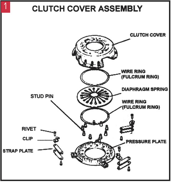
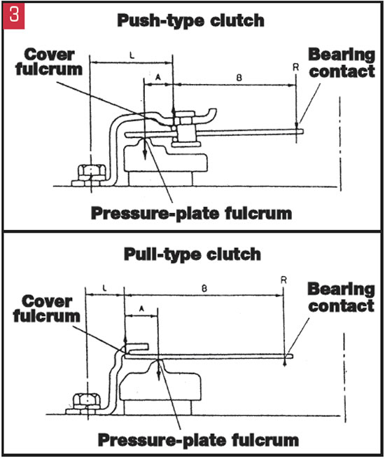
The diaphragm-spring design consists of a ground pressure plate on which the clutch disc rides, a stamped or forged clutch cover that contains the diaphragm (Belleville) spring, fulcrum rings on which the diaphragm spring pivots, and strap plates that lift the pressure plate away from the flywheel when the clutch is disengaged. The push-type diaphragm spring is designed to release the clutch clamp load when the release bearing travels forward and depresses the center of the diaphragm spring toward the flywheel. As the diaphragm spring pivots on the fulcrum ring, the outer diameter moves toward the transmission and the strap plates lift the pressure plate away from the clutch disc. This amount of travel is very small, and in many instances as little as 0.050 inch air gap between the pressure plate and the clutch disc is sufficient to disengage the engine power flow from the transmission.
On pull-type diaphragm-spring pressure plates, the release bearing is mated to the diaphragm spring, and when the clutch pedal travels it pulls the diaphragm spring toward the transmission. As the diaphragm-spring outer diameter moves toward the engine, the strap plates lift the pressure plate away from the clutch disc.
There are other considerations in the diaphragm-spring pressure-plate (clutch cover) design. The first is what happens when the clutch-disc friction material begins to wear. The thickness of the disc decreases as friction material is worn away, and the angle of the diaphragm spring changes, moving the inner diameter of the cone that the release bearing contacts toward the transmission. This causes the release bearing to have less travel before it contacts the diaphragm spring and results in a “high” pedal engagement.
Another important issue is movement of the clutch cover when the clutch is being disengaged and engaged. This movement is called deflection and greatly affects the clamp load of the clutch, which is the ability of the clutch components to handle the torque load of the engine. Deflection increases with friction-material wear and changes as clutch-cover temperatures increase during use.
The clutch function is similar to the function of braking. As the engine provides kinetic energy (the energy of motion) to the flywheel, the friction bond between the flywheel, clutch disc and pressure plate turns some of that energy to heat as the clutch is engaged and disengaged. Unless there is slippage with the clutch fully engaged, no heat should be generated once the clutch has achieved full clamp load. Stamped clutch covers made of cheaper steel tend to deflect more than heavier stamped or forged covers, shortening clutch life.
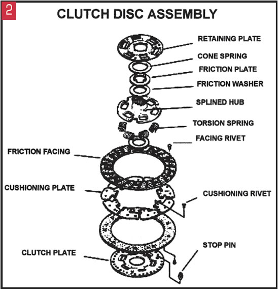
The clutch-disc assembly appears to be a simple product but is actually a complex design. The average clutch disc consists of a clutch plate, a cushioning plate that has a shallow S-shaped curve to which friction facings are bonded or riveted, a splined hub in which torsional-vibration springs are contained, friction washers, a friction plate, a cone spring and a retaining plate.
The amount of engine torque that a clutch is able to handle depends on the size and diameter of the friction facings. The torsional-damper assembly is critical to driver comfort, as it has to filter out NVH (noise, vibration and harshness) transmitted by the engine into the driveline. The engine creates harmonic vibrations because of its firing pulses, and these pulses vary greatly between four-, six- and eight-cylinder engines and between gasoline and diesel powerplants.
If these pulses or harmonic vibrations are not properly damped, the result is transmission gear rattle in neutral and in drive mode. This does not hurt the transmission but will cause the customer to bring the vehicle in with a noise complaint. The problem is extremely complex, as there are different engine harmonics at idle and different engine speeds, so the disc must be engineered to work across the whole engine power band. This entails different sizes and types of damper springs in the splined hub, some of which act on idle-speed vibrations and others that shield the powertrain from speed-induced vibrations. In some applications a dual-mass flywheel is used to further damp the engine harmonics.
The friction material selected for each application is specific to the torque produced by the engine. The facings must be designed to handle enough torque, retain holding power under high-heat conditions and have a smooth friction coefficient at engagement to enable the driver to leave from a dead stop smoothly.
Many different friction compounds are available, ranging from a bonded, woven organic material through cerametallic and carbon facings. The most-common passenger designs are the woven organic material, which now must be asbestos free. The cerametallic and carbon facings generally are associated with heavy-duty performance and racing applications where driver comfort is not the paramount concern. The friction material is bonded or riveted to the cushion segments, which play an additional part in making the clutch engagement as smooth as possible.
If you look at the edge of a clutch disc, you will see the shallow curve in the spring steel of the cushion plates between the two clutch friction facings. As the clutch is engaged these cushion plates provide an initial level of drag (friction) to the flywheel and pressure plate, and then as the clamp load increases they flatten out. This provides for the smoothest clutch engagement possible.
There are many considerations in clutch design and engineering, and the replacement clutch set must be matched correctly to the vehicle for proper operation. It is easy to forget the big picture when you have clutch-related problems, but you have to look at the whole vehicle.
For instance, powertrain mounts are important to proper clutch operation. Pushing the clutch pedal puts a force greater than the clamp load on the release bearing and diaphragm spring to release the clutch. This can equal thousands of pounds, and if the powertrain mounts permit the engine to move forward under this load, the clutch cannot release properly, causing premature wear and clashing shifts. A worn crankshaft thrust bearing will do the same thing by permitting the crank, flywheel and clutch assembly to move forward and away from the release bearing.
A tow-truck operator once brought me a truck in which he had installed several new clutches within weeks, only to have them fail. After a road test, I opened the hood and asked him to engage and disengage the clutch while I watched. As he stepped on the clutch pedal, the “Z”-bar linkage lifted the entire body off the frame. The body mounts had worn out, and instead of releasing the clutch completely he was moving the body, which caused a poor clutch release and early failure.
Oil leaks, hydraulic problems, out-of-tune engines, worn front-bearing retainers and driver abuse create many clutch failures that will make you a victim if you are not up on your game. A good tip with younger drivers of “hot” machinery is to walk around the car and look at all the tires. If on a rear-wheel-drive car the rears are bald and the fronts are pretty good, it gives you a hint that this guy likes to leave in a cloud of tire smoke when the light changes. This will not be your problem if you make him understand that it is his money he is spending and not yours. A further area of protection after you do a clutch repair is to take a test drive with the customer driving, which may be an eye-opening experience. At that point you can make some subtle suggestions about their driving habits to help them prolong THEIR investment.
There is a tremendous amount of design technology and engineering in every new clutch set you buy. Understanding how all these components work together will make diagnosis easier and help you prevent failures under warranty.