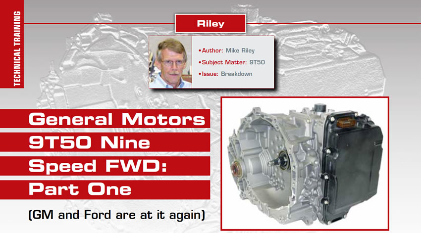
Technical Training
- Author: Mike Riley
- Subject Matter: 9T50
- Issue: Breakdown
(GM and Ford are at it again)
Back in early Y2K General Motors and Ford demonstrated some impressive common sense by jointly developing a brand-new six-speed automatic transmission. The 6T70 / 6F50 and 6T40 / 6F35 transmission families have undergone countless changes since 2007 and are used in a variety of different models of vehicles currently.
There has been a rather lengthy learning curve by the OEMs and aftermarket when it comes to failures and repairs of all of the six-speed models of transmissions. They are, however, much better today than they were at the beginning.
Due to ever increasing fuel economy demands OEMs have been forced into developing even more efficient engines and transmissions, which is why there have been an endless number of transmission platforms developed and pressed into service, (CVT, DCT, EVT and step type models with more gears).
Seven- and-eight speed transmissions were not good enough, which is why there are now nine- and even ten-speed transmissions on the street today. Schwinn Bicycle can’t even keep up.
When the call to order came GM and Ford once again put differences aside and went to work on a FWD nine speed and RWD 10 speed. GM basically took the lead on a nine-speed transmission, leaving Ford to polish off the 10 speed.
To avoid major development cost, the OEMs apparently decided to modify and carry forward the six-speed platform. To squeeze out three more gears without major changes required some innovative engineering changes, which is exactly what they did. The question now is how successful will the units be.

On the GM side of the fence there are currently four transmission models, the 9T45, 9T50, 9T60 and 9T65 that require different RPO codes based upon model of vehicle. The first nine-speed was launched in the 2017 Malibu. The 2018 Traverse, among others, also received the nine-speed transmission.
The GM nine speeds are based upon the 6T41 (GEN 3), which switched to the remote access pump just like the 6T70 transmission. Externally, nine speed models that are equipped with the start-stop option differ from the six speeds, which have that feature, by the way the transmission remains pressurized while the engine is off. Instead of an electric motor/pump that kicks on to maintain pressure the nine speed transmission has a spring-loaded accumulator that remains charged while the engine is on and provides pressure to the unit when the engine is off. The accumulator assembly is bolted to the top of the bell housing/case on models that require it.
Upgrading to a nine speed certainly required changes to the vehicle software as well as electrical components within the transmission, (i.e. solenoids, sensors and electrical connections). One six-speed feature that did not carry forward is the TEHCM, which should be to everyone’s delight.
Changes relating to the hard stuff involve three main components. The first item involves the one-way clutch, which is just a bit different from the diode, contained in six speed models. The diode used in the 9T50 does more than freewheel one way and lock up the other and is referred to as a selectable or selective one-way clutch. Another item is the addition of a rather unique clutch pack that is a combination of a rotating clutch and stationary brake. Lastly, is a change to the planetary system involving the reaction planet used in six speeds, which is basically a simple planetary design. The 9T50 actually uses a compound planetary in that position. The nine speed is only slightly heavier than the 6T.
Ford took a somewhat different approach related to the FWD nine-speed transmissions. They decided to use the unit as an eight-speed due to the minimal gain in fuel economy that the extra gear provides. Beauty is in the eye of the beholder, as they say. The Ford eight speed is being released in specific models beginning in 2019 with three different versions. The 8F35 and 8F40 are patterned after the 6F35 (one piece case) whereas the 8F57 resembles the 6F50 (case with end cover). Who knows, at some point Ford may add the missing gear to be in sync with GM.
At first glance the 9T50 could easily be mistaken for a GM six speed. Not only is the weight about the same between the two transmissions the overall length is pretty close as well. Upon disassembly the transmission type becomes real apparent. Following are some highlights:
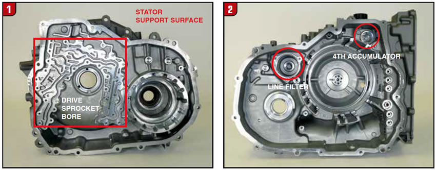
Bell Housing – The Bell housing splits from the case just like a 6T40 however, the appearance of the backside of the housing is far from a 6T40. As stated, the 9T50 has more in common with the 6T41 (Gen 3) due to the implementation of a remote access pump, (Figure 1). The cavity for the final drive carrier and ring gear is certainly common looking and in fact the carrier to housing bushing and axle seal are the same as a six speed. As usual, GM models use a Bell housing to case gasket.
It is the stator support area which may not be very familiar to anyone that has not rebuilt a GEN 3 6T41 utilizing a remote access pump. The area in question is sizable and actually uses a thin metal plate between housing and support. It’s considered a VB spacer plate by GM and has a couple of beads of silicone on one area. There is also a pocket cut into the Bell housing at the torque converter bore to accommodate a thrust washer for the pump drive gear similar to the 6T70 / 6T41 design. The 9T50 also uses a chain snubber just like a 6T40.
Case – Viewing the case from the Bell housing side at first glance looks like a normal six speed. There is a deep cavity that contains all of the major components including the clutch drum sleeve, which bolts to the back of the case. Even the bearing surface for the driven sprocket is comparable. The nine speeds also use rubber seals which press into a thin metal plate which fits between the case and Bell.
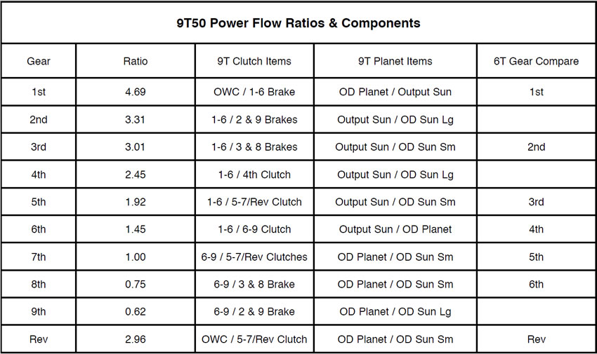
A couple of the key distinctions from six speed models are that the nine speeds are equipped with an auxiliary (line) filter and a 4th accumulator piston and spring that were added to the case. The accumulator is similar to one used in a 6T70 valve body, (Figure 2). The axle shaft bushing and seal are the same that are used in the 6T40 case. The large support snap ring is also a bear to remove and install.
The valve body side of the case also looks fairly common to anyone that has done a six speed. The linkage mechanism and internal mode switch are nothing new and there is a hole for the output speed sensor and bolt. The valve body assembly bolts to the case as usual. One noticeable difference is that the nine speeds use five rubber tube seals between the valve body and internal supports instead of two that are used in the 6T40, (Figure 3).
Pump – Although the remote access pump in the 9T50 looks like the Gen 3 6T41 very little is the same. Beyond the basic bolt pattern and overall shape is the issue of the input shaft bore. To accommodate added torque capacity the diameter of the input shaft was increased where it goes through the stator support. That change not only affected the input shaft bushings but the input shaft seal as well.
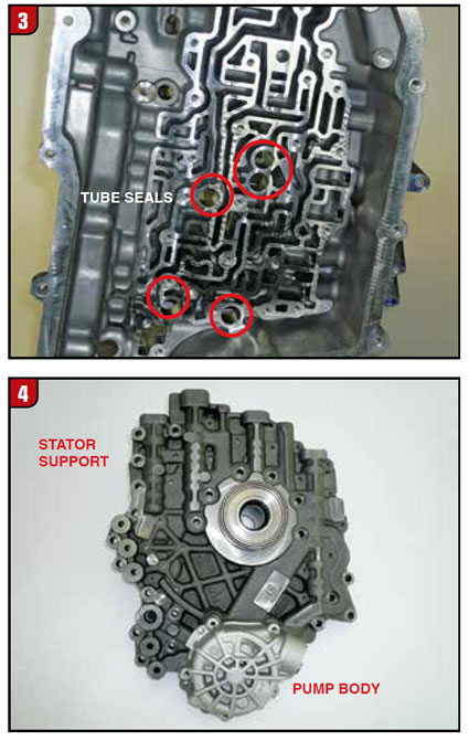
The front side of the stator support contains a cavity that accommodates the pump drive and driven sprockets along with the chain. There are plastic washers on each side of the pump drive gear, which are the same as the 6T41. The backside of the stator support is where the pump body bolts to, (Figure 4). The pump shaft extends through the stator support and splines to the driven gear. There is a metal clad seal in front of the shaft ball bearing, which is also the same as a six speed.
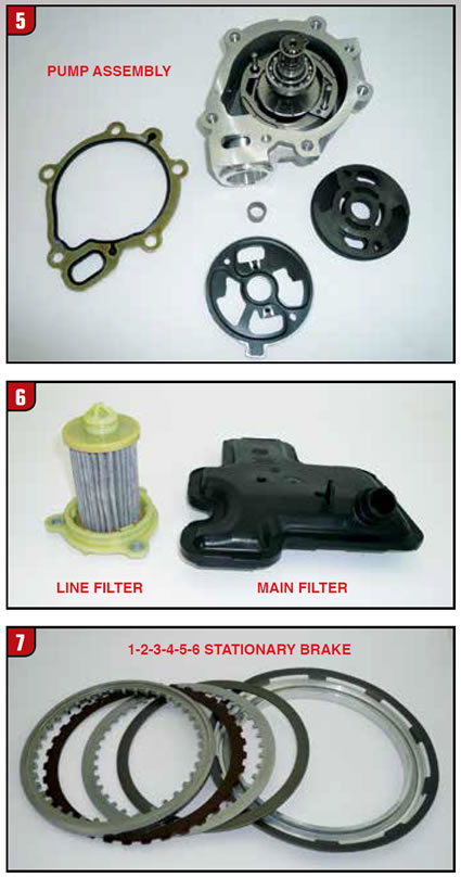
The pump assembly is rather compact and is a vane type dual chamber design. The pump assembly consists of a rotor, vanes, stationary slide, end plate and shaft. Not only is there a gasket between the pump body and stator support but there is also a gasket between the pump end plate and support surface, (Figure 5). There was a dimensional change to the slide, end plate and gasket so use caution when interchanging components. Second design parts will have an identification mark as a reference and a GM bulletin was issued concerning the change.
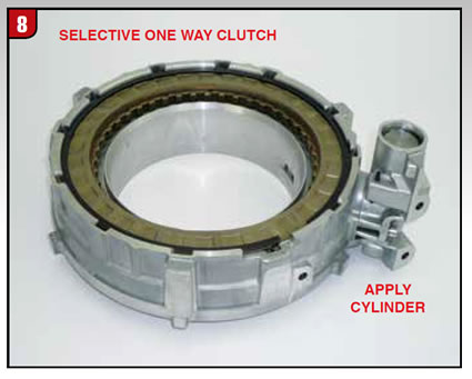
Filter – The main filter is fairly typical and resembles the 6T41. The outlet tube presses into a top hat seal which is located in the bore of the pump assembly, (Figure 6). In addition to the main filter GM decided that the 9T50 needed help, which is why the line (auxiliary) filter was developed. The line filter is a cartridge type that is held in position by a three-bolt cover, which has an O-ring. There is also an O-ring that goes on to the tip of the filter.
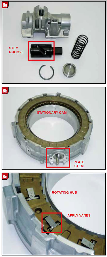
Stationary Brake #1 – With the Bell housing and related components removed the output sun gear is accessible. The clutch pack that meshes with and holds the output sun gear stationary is the 1-2-3-4-5-6 Stationary Brake or 1-6 Brake for short. As the name applies those are the gears that require the sun gear to be held just like the 1-4 Brake on the 6T40.
The configuration is a bit different from the 6T40 in that the frictions are external tooth and the steels are internal tooth, (Figure 7). The pack requires two frictions and two steels and also utilizes a cushion spring. The piston is aluminum with a sizable return spring.
The aluminum support that contains the clutch assembly is not a normal support but rather the front side of what GM calls a selective (or selectable) One Way Clutch. The component is held into the case by another, big monster tapered snap ring just like the six speeds.
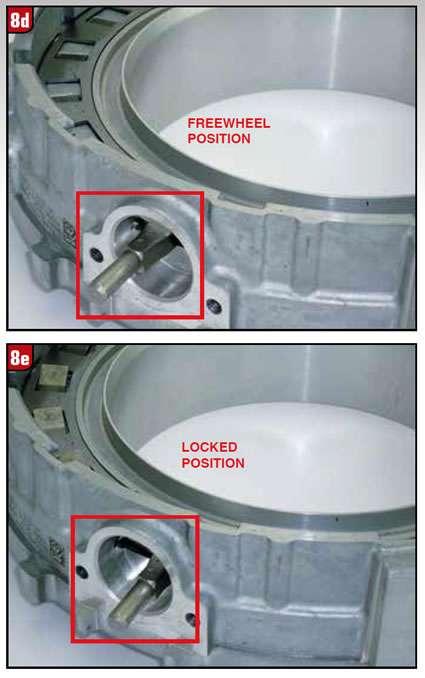
Selective OWC – One design improvement that GM came up with beyond the six-speed transmission had to do with the diode OWC. The 6T40 diode functions like all other one way clutches in that it locks up one way and free wheels the other. The 9T50 takes it one step further by adding the ability to lock up in both directions under certain conditions. The SOWC housing has an oil-operated cylinder which bolts to the outside and is fed directly from the valve body via two rubber tubes, (Figure 8).
The cylinder is fairly basic. At one end there is a small snap ring that retains a metal cover and O-ring. Use caution when removing the snap ring due to the spring underneath. The apply piston is rather unique because there is a groove in it that is somewhat spiral, (Figure 8A). As the piston strokes back-and-forth it moves a stem of the diode in a certain manner.
The stem (or pin) that the cylinder operates is visible with the cylinder removed, (Figure 8B). The stem actually slides side to side within the hole where the cylinder is located. Internally, the stem is attached to a big round plate that is basically the size of the housing. The plate has cut outs all the way around to enable several vanes to raise and lower.
All Mechanical Diodes are comprised of a stationary top cam with ramps cut into the underneath side in a circular manner in order to allow the locking elements (which somewhat look like pump vanes) to rotate and ratchet one way and lock up the other. The edges of the vanes are cut at an angle and have very small springs underneath, (Figure 8C). The pockets for the vanes are cut into the rotating hub and all slant in the same direction.
Where the 9T50 diode differs from a six speed is found on the underneath side of the rotating hub. There is actually another set of vanes cut into the aluminum housing with ramps of a different design cut into the bottom of the rotating hub. What separates those vanes from the ramps of the hub is the big round plate that is connected to the stem, (Figure 8D). Looking at the illustration the plate is rotated in a clockwise manner forcing the vanes to be flat. In this position the hub is free to operate in a normal manner by freewheeling one way and locking the other with the top set of vanes. Once the plate is rotated counterclockwise the bottom elements are allowed to pop up and contact the bottom ramps of the rotating hub thus preventing the hub from rotating in either direction, (Figure 8E). In this mode the diode is nothing more than a stationary component. By implementing this design GM in effect was able to eliminate the low /reverse clutch used by the 6T40.
Stationary Brake # 2 / 4th Clutch – Although one clutch pack was reduced in the nine speeds from what is used in six speed transmissions, there is actually a net gain in friction packs of one over total packs used in six speed models. The 9T50 has six friction packs versus five used in the 6T40.
Directly behind the selective OWC is another large aluminum support that contains two pistons, (Figure 9). The pistons are fed apply pressure from the valve body through two more rubber tubes in the case. The large aluminum piston is used for a 2/9 stationary brake, which is the second position in the transmission. This friction pack is one of two added to the 9T50 in order to squeeze out three extra gears. There is really nothing special about the 2/9 clutch assembly except for the lip seal, which is rather unique. What is different in the aluminum support has to do with the other piston, which is for the 4th clutch that happens to be steel, (Figure 9A).
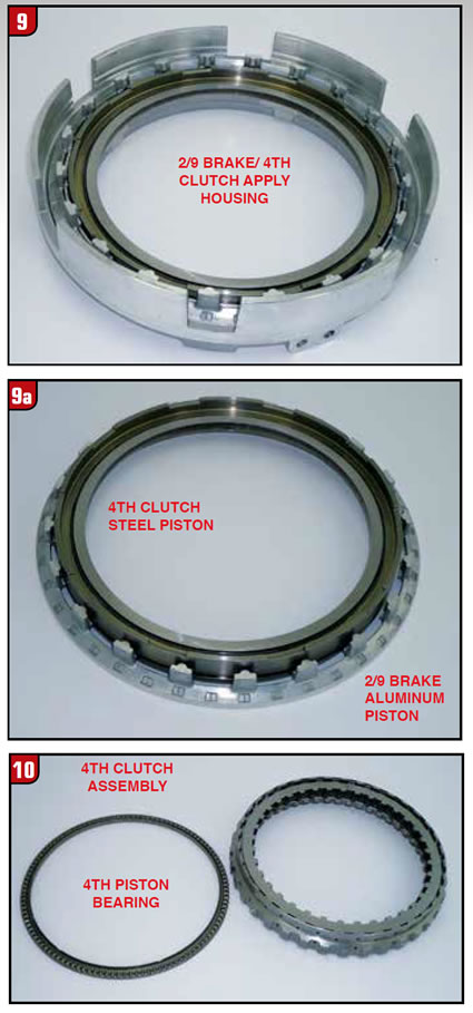
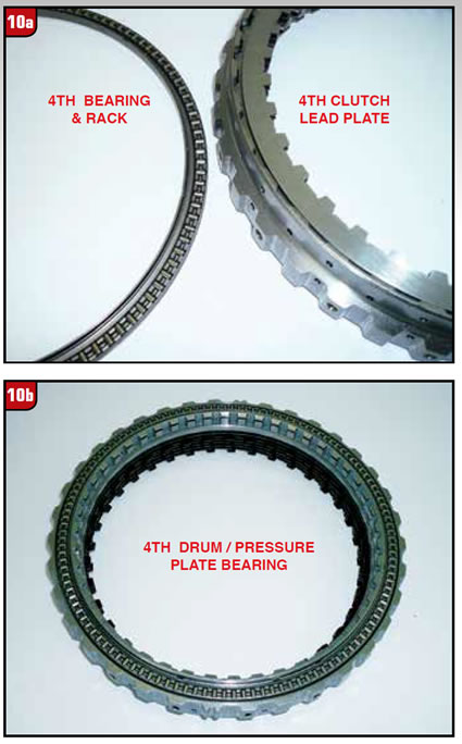
Traditionally transmissions have used either a rotating clutch or a stationary brake in regard to friction elements. The 4th clutch deviates from that model in a big way. Although the apply piston is stationary the 4th clutch drum is not because it does rotate at times. What makes this possible is a large bearing that goes between the steel piston and 4th friction pack, (Figure 10). The bearing assembly is comprised of one large bearing and one large race. The race goes directly against the first steel plate in the clutch pack, (Figure 10A). The bearing rotates against the steel piston, which means the piston itself is a bearing race. It remains to be seen how well the piston will hold up. The plot thickens even more because on the opposite side of the 4th clutch drum is another large thrust bearing which is crimped into the drum, (Figure 10B).
The clutch drum, actually splines to a sun gear flange however, not quite like other transmission types. There is actually a Belleville spring between the drum and flange to enable a small amount of front to back movement during clutch apply and release. A snap ring holds everything together.
The final component in this concoction is the backing plate, (Figure 11). Like the other items mentioned the backing plate is also kind of special. This one backing plate is actually utilized for three different friction packs, the 2/9 stationary brake, 4th clutch and 3/8 stationary brake. Since the bearing of the 4th drum rides directly against the backing plate it means that the plate is tough as nails as well.
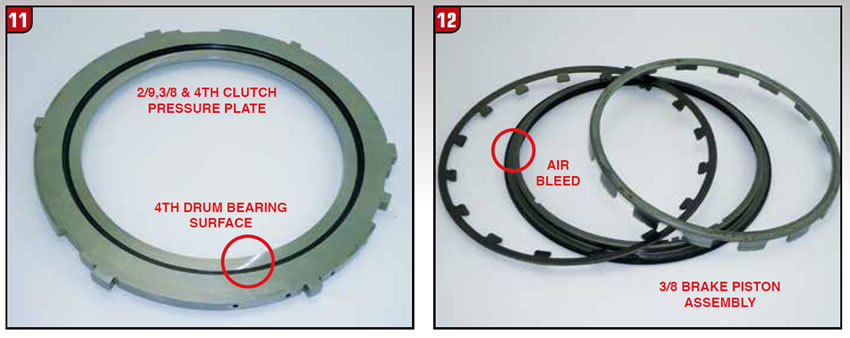
Stationary Brake #3 – The third and final stationary brake used in the 9T50 is positioned in the bottom of the case and is the 3/8 brake assembly. The stack up is fairly similar to the 2/6 stationary brake used in the 6T40 application. Unlike the other pistons the 3/8 piston is bonded rubber, (Figure 12). In addition to the Belleville return spring is an apply ring that fits directly against the clutch pack. The piston does have a small air bleed, which must be positioned at the top. One plus in all of this is except for the large beveled case snap ring, all four Belleville/support snap rings are the same.
In Part Two, we will be taking a look at the rotating clutches, planetary gear sets and more.


