Technically Speaking
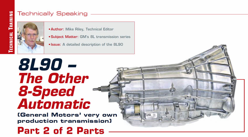
- Author: Mike Riley, Technical Editor
- Subject Matter: GM’s 8L transmission series
- Issue: A detailed description of the 8L90
Part 2 of 2 parts
Eight-speed automatic transmissions have been around since 2007, but General Motors was a little late to the party, due to development, manufacturing and other concerns.
By 2014 GM released the 8L90 in the Cadillac ATS. A year later, the 8L transmission series had spread out to the Corvette and trucks such as the Silverado and Yukon. Currently, GM offers two models of eight-speed transmissions, the light-duty 8L45 and heavy-duty 8L90. When GM developed the 6L80/6L90 transmission series, they were loosely based upon the ZF 6HP family of transmissions. The 8L90 also has a ZF thumbprint on it, though somewhat less than the previous six speeds. One welcomed departure from ZF was the absence of an internal TCM in the GM units.
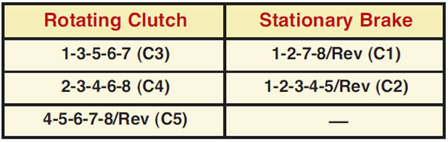
The 8L90 uses numbers to describe when a friction element is applied like GM six speeds, but the numbering is somewhat more involved with the eight speeds due to more gears. Friction elements are listed accordingly:
Part 2 will begin with a discussion of the planetary gears sets.

Planetary gear assembly
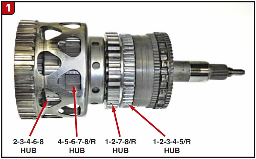
Although there are four planetary gear sets, GM did a great job in compressing the space needed overall. From the connecting shell in the front to the removable splined output shaft in the back, the nested planet assembly is certainly compact (Figure 1). Four of the five clutch hubs are also part of the assembly.
Direct/overdrive planetary
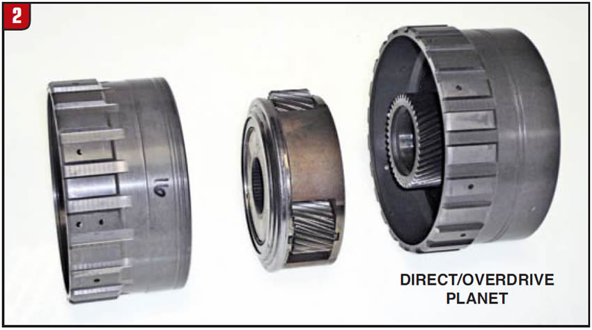
The first planetary gear set in the stack up is the direct/overdrive assembly. As with other later-model transmissions, gear-set components are not always clear-cut as to the layout. The first item in this set is a ring gear that also doubles as the 2-3-4-6-8 clutch hub. There is a thrust bearing between the ring gear and clutch housing. The next item is a planetary that splines to the output planet shaft and has a captured thrust bearing on the backside. On the front side is another thrust bearing retained by a metal baffle. The third item has three functions, first as the sun gear, next as the 4-5-6-7-8/R clutch hub and lastly as the ring gear for the input carrier (Figure 2). The assembly is retained with a spiral snap ring and the sun gear has a press in bushing.
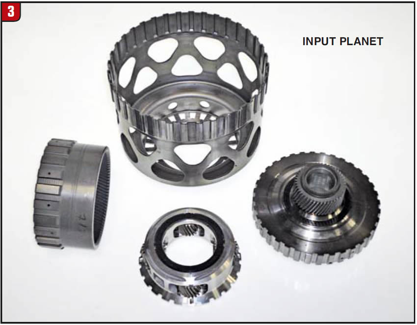
Input planetary
The next planetary set down the line is the input planet that is also somewhat unique. As stated, what drives the input planetary is the previous sun gear/ring gear assembly. In addition, the aluminum planet carrier is connected to a driving shell that splines to the 1-3-5-6-7 clutch housing and can be driven directly by the input shaft (Figure 3). The input sun gear has more than one function as well, since it is splined to the reaction sun gear and is also attached to the 1-2-7-8/R clutch hub. The sun gear contains a front and rear bushing and the planet carrier uses two plastic thrust washers.
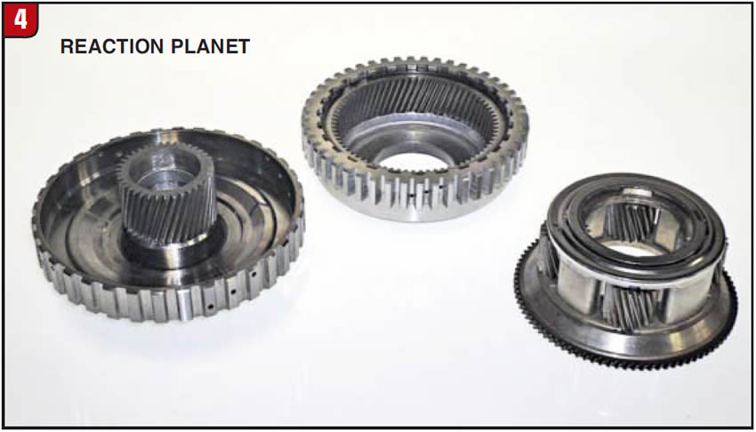
Reaction planetary
The third assembly is the reaction planet set, which is comprised of the dual sun gear, ring gear and planetary carrier (Figure 4). The ring gear is splined to the aluminum 1-2-3-4-5/R clutch hub and has a thrust bearing on the front of the assembly. The planet carrier also has a thrust bearing retained by a metal baffle and the carrier is splined to the output ring gear. The retaining ring is also a spiral design.
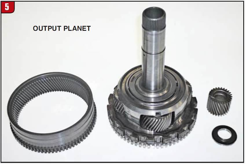
Output planetary
The last assembly is the output planet set, which is what the output shaft splines to. The set components are the output ring gear, planet carrier and sun gear (Figure 5). The intermediate speed-sensor teeth are cut into the outside of the ring gear. The planet carrier contains a shaft that splines to the direct/overdrive planet carrier and also has a thrust bearing retained by a metal baffle. Not only are the park-gear lugs made to the carrier, but the output speed-sensor teeth as well. To say that the output sun gear is small would be an understatement, but small it is. The sun gear splines to the intermediate shaft and has a rear thrust bearing that goes next to the output shaft. Many of the planetary components can be removed from the back of the case.
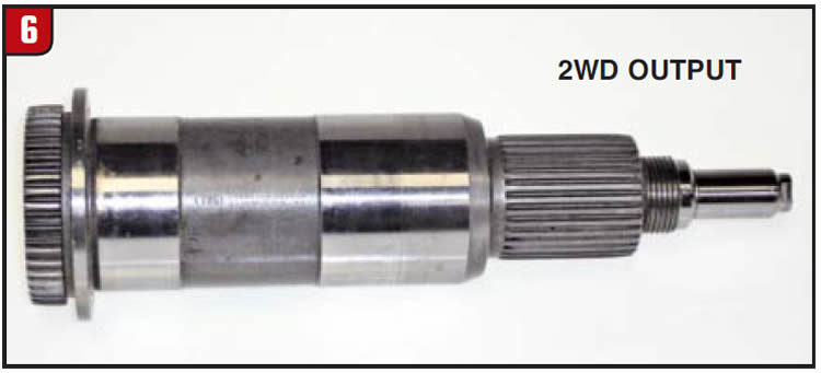
Output shaft
In order to improve interchangeability, GM designed the output carrier and output shaft to be a simple spline fit (Figure 6). The output shaft illustrated is a 2WD design that uses a bolt on flange; however, other designs such as 4WD can be easily installed.
Valve body
Although GM did copy many of the attributes of the ZF 8HP design, they certainly went one step beyond with the valve body/pump assembly by having everything integrated into one casting. Whether this design is advantageous or not remains to be seen; however, time will tell. The valve body itself is somewhat large and contains nine solenoids, seven PWM and two on/off (Figure 7). The solenoid resistance values are typical with the PWM at about 5 ohms and the on/off at about 12 ohms. GM did go to the effort to cast a letter into the valve body for each solenoid to help with identification.
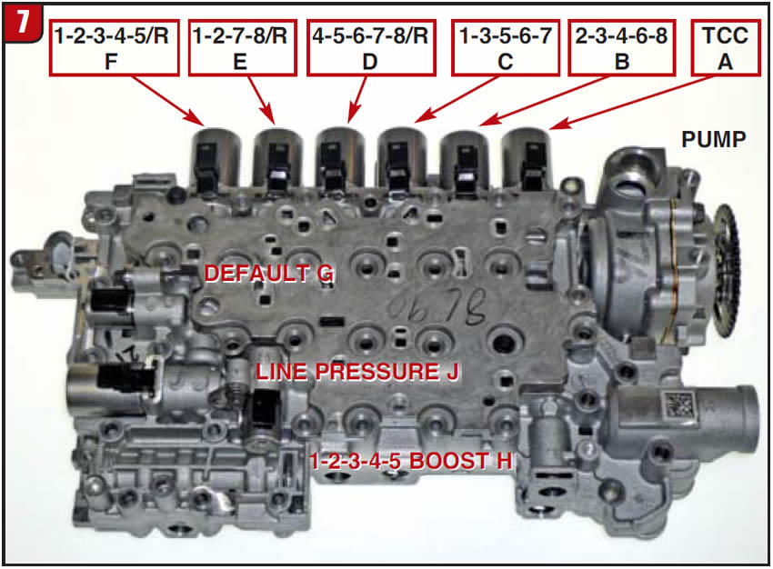
The valve body contains the usual suspects (valves and springs) and has one accumulator piston for the front 1-3-5-6-7 clutch pack. On regular valve bodies, there are 10 check balls (one large and nine small) and seven small damper valves and springs to smooth out solenoid pressure, like the 6T70.
There are three check balls under the cover plate, two check balls in the pump body and five in the solenoid body.
Beginning in 2016 GM has added a start-stop accumulator assembly to the 8L90 that requires an additional solenoid and two more check balls to the valve body, making a total of 12. The accumulator housing will bolt to the valve body at the back of the case.
Solenoid design
Although GM decided against going mechatronic (internal TCM), it does not mean that solenoid operation is like back in the old days. In addition to whether the solenoid is normally open or normally closed is the issue of finite calibration. There are three basic designs of the PWM solenoids, which can be identified by the electrical connector or stamped part number (Figure 8). Three of the solenoids have part No. 24272280, one with part No. 24272281 and three with part No. 24272282. The electrical connector tab design prevents installing the wrong harness. It is still advisable to mark solenoids before removing.
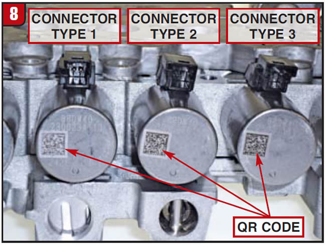
Just as Ford did with the 6R 140, GM has instituted the TUN & PUN scenario. When replacing certain items such as the transmission, valve body or individual solenoids, correct numbers are imperative. The TUN (transmission unique number) is located on the tag at the side of the transmission. The PUN (part unique number) is located on the valve body or solenoid along with QR labels. Refer to these numbers for any major repair.
Pump assembly
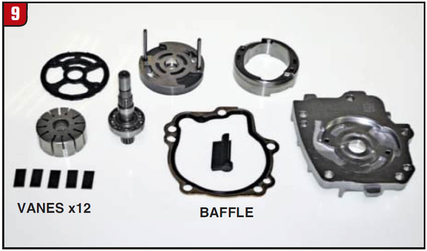
The GM remote access pump is almost a carbon copy of the ZF design, although the ZF pump is a separate part. The pump is a dual-chamber vane-type assembly that is certainly compact (Figure 9). There are 12 vanes for the rotor and there is a gasket between the cover and valve body casting. There is a bonded rubber plate that goes between the outer sleeve/end plate and valve body casting that has now been redesigned to a thick metal plate with two gaskets. There is also a plastic baffle that is used to limit cavitation that must be installed. Ensure that all components are reassembled correctly to avoid issues.
Electrical harness
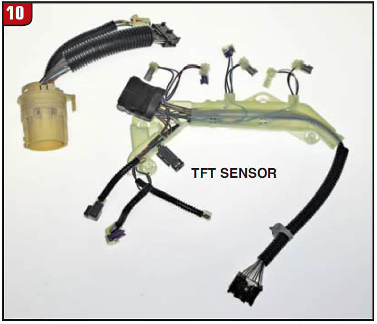
There is no shortage of wire in the 8L90, all of which terminates at a rather large case connector. The solenoid harness assembly not only plugs into all of the solenoids but also plugs into the IMS, sensor plug and case connector plug as well (Figure 10). The harness also contains the TFT and plastic support bracket. Use caution not to damage any of it.
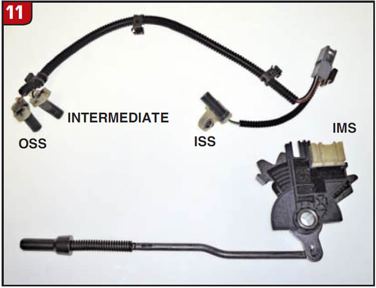
Sensor assemblies
The 8L90 has an IMS (internal mode switch) comparable to most other later model transmissions. The switch is part of the shift mechanism and is handled accordingly. There is not one but three rpm speed sensors (Figure 11). The ISS is to the front of the transmission, whereas the intermediate and OSS sensors are at the back right next to each other. Hold-down bolts are also torque to yield that should be replaced.
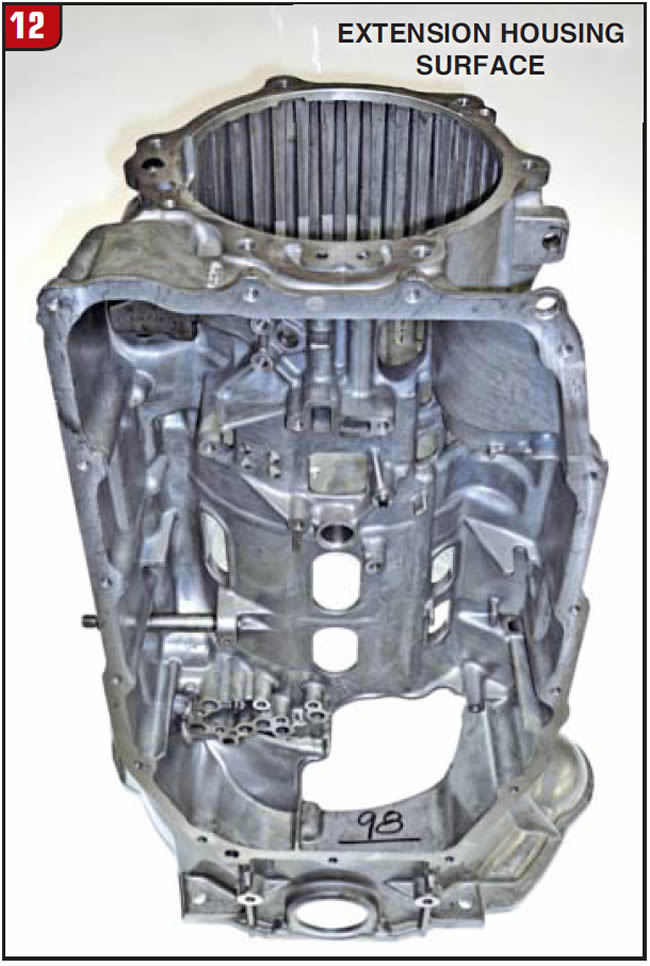
Case assembly
The 8L90 case is die-cast aluminum and is fairly wide open, making most everything accessible (Figure 12). Application will dictate bell-housing design and as stated the transmission type is cast into the side of the case. Cooler lines are a push in type that will bolt to the side of the case and have two seals that are pressed into the case.
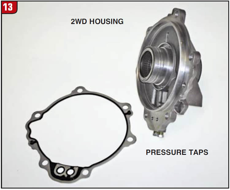
Extension housing
The extension housing bolts to the case and design will vary depending on 2WD or 4WD applications (Figure 13). The housing in the illustration is for 2WD. The extension housing contains the cavity for the 1-2-3-4-5/R apply piston and has caged bearings for the output shaft. There is a bonded rubber gasket that goes between the extension housing and case. The housing also contains the line pressure test plug.
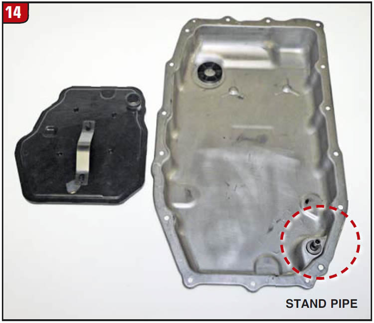
Pan and filter
When servicing an 8L90, drop the bottom pan to expose the filter. The filter is an all-plastic design and pushes directly into the valve body assembly (Figure 14). The pan gasket is a reusable bonded rubber design like other GM transmissions have. The stand pipe is positioned at the front edge of the pan. Always follow fluid change and fluid check procedures to ensure the proper fluid level.
In conclusion
When doing repairs or replacement of the transmission, programming is vital to ensure proper operation. The GM eight speed not only has a fast-learn capability but is also adjusted by shift-adaptation procedures. Follow recommended procedures based upon application to avoid short-term or long-term issues.
Special thanks to the folks at TransTec for providing the 8L90 unit used for illustration purposes.


