Technically Speaking
- Author: Mike Riley, Technical Editor
- Subject Matter: GM’s 8L transmission series
- Issue: A detailed description of the 8L90
Part 1 of 2 Parts
One example of how time flies by is the fact that there has been an eight-speed automatic transmission on the road since 2007. The Aisin Corp. beat everyone to the punch when they developed the AA80E for use by Lexus. The next eight-speed automatic to hit the streets came from ZF in late 2009 and was used by Audi and BMW. Even Hyundai got into the mix by releasing the A8LR1 and A8TR1 in 2011.
It took GM just a bit longer to develop and launch a homegrown eight-speed transmission, in order to accommodate a variety of vehicles. Finally, in 2014 GM released the 8L90 in the Cadillac ATS. A year later, the 8L transmission series had spread out to the Corvette and trucks such as the Silverado and Yukon. Because of manufacturing delays GM actually purchased the Aisin AA80E (TL80-SN) in 2013 for use in the Cadillac CTS, which is basically like the Lexus model. The RPO code for the 8L90 is M5U.
Currently, GM offers two models of eight speed transmissions, the light-duty 8L45 and heavy-duty 8L90. There are 2WD and 4WD versions and the case assembly is substantially different between Corvette and truck applications at the Bell housing area. As is customary, the Corvette unit has virtually no bell housing compared to the truck application illustrated. To help with identification the model number is cast into the case assembly on the driver side behind the shift lever (Figure 1).
When GM developed the 6L80/6L90 transmission series, they were loosely based upon the ZF 6HP family of transmissions with traditional GM traits sprinkled in. The 8L90 also has a ZF thumbprint on it, although somewhat less than the previous six speeds. Certain ZF characteristics that the 8L90 is equipped with include a remote access pump, five friction elements, four planetary gear sets and a slew of solenoids. One attribute that GM did not copy from ZF, fortunately, is not having an internal TCM. There are enough mechatronic transmissions to deal with already, so thanks to GM.
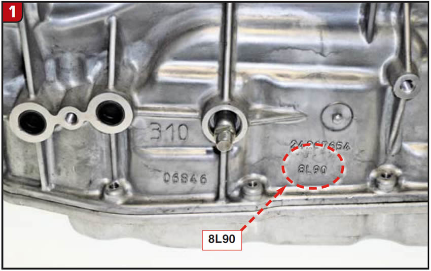
Using actual numbers to describe when a friction element is applied is a good thing and certainly helps when diagnosing problems on transmissions like GM six speeds, but as they say about too much of a good thing, etc. Using that approach to describe eight- speed friction elements can be a bit more involved, to the point of stating when elements are not applied, which would be shorter. To illustrate is the following:
As with many later model transmissions, checking the fluid level or changing transmission fluid may be a chore. There is no dipstick, therefore all of the tinkering must be done from underneath the vehicle. In addition, it is advisable to have a scanner hooked up to verify fluid temperature. The push lock fill plug is on the passenger side of the case and the pan is outfitted with a stand pipe. When the correct transmission temperature is achieved (about 100 F), raise the vehicle and remove the stand pipe plug to see whether fluid will trickle out or not. If needed, add fluid through the fill hole until it does. Based upon vehicle model, the transmission will require approximately 11½ quarts of Dexron HP fluid.
If line pressure testing is required, there is a test plug on the extension housing. There are two plugs on the housing with the line pressure being on the left and the 1-2-3-4-5/R plug on the right. Using a scanner, actual line pressure can be compared to commanded line pressure, which can approach 300 PSI.

Case Cover
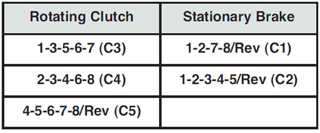
Unlike the ZF 8HP, which is a one-piece case design, the 8L90 does have a bolt-on extension housing that will provide access to certain items at the back end of the transmission. Most components, though, will be removed from the front end. The first item to be removed from the transmission is the case cover, which does resemble the ZF unit (Figure 2). Do not assume that the cover will just fall out after the bolts are removed. The O-ring that goes around the cover is sizable and can create a fair amount of drag. In addition, there is a gasket on the backside that can stick. Fortunately, there are threaded holes available to install pump pullers to easily remove the aluminum cover. With the exception of the converter seal and drive gear thrust washer, there is not much else to the cover.
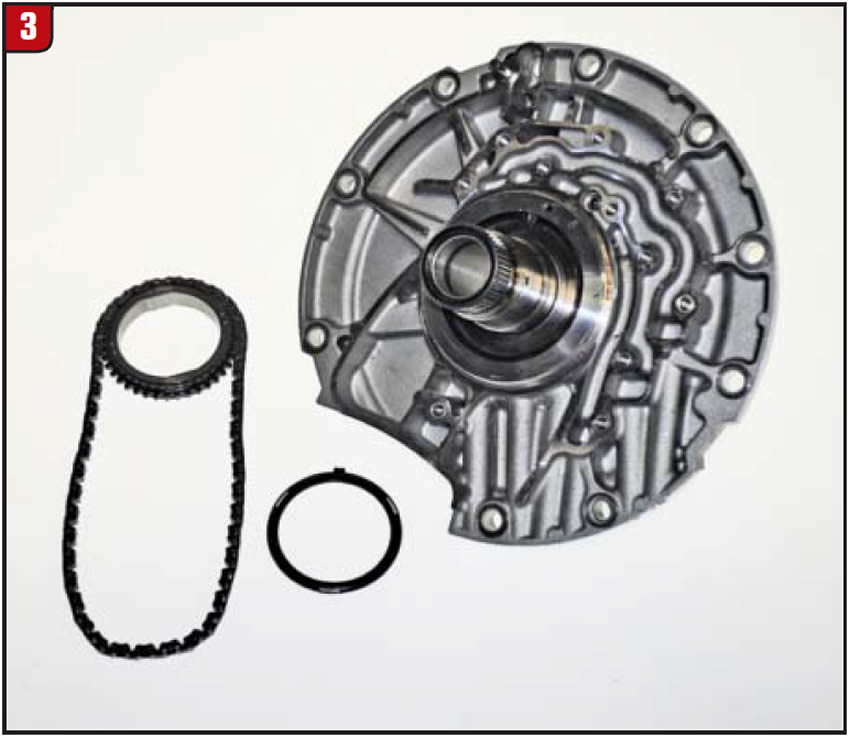
Stator Support
With the cover removed, the stator support, pump drive gear and chain are exposed. Since the 8L90 has a remote access pump, the stator support is merely a cover with a shaft (Figure 3). The stator shaft has a journal for the converter bushing and sealing ring, an input shaft bushing and does have two sealing ring grooves. There is also a thrust washer for the backside of the drive gear. The drive chain is similar to the 6T70 and the drive gear can face either direction. Before removing the stator support, the drive gear and chain must be removed and that requires an additional operation.
At this point rotate the transmission and remove the pan and filter to expose the pump-driven gear. With the filter removed, the drive chain baffle will be exposed (Figure 4).
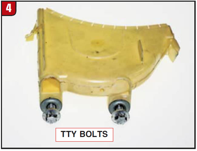
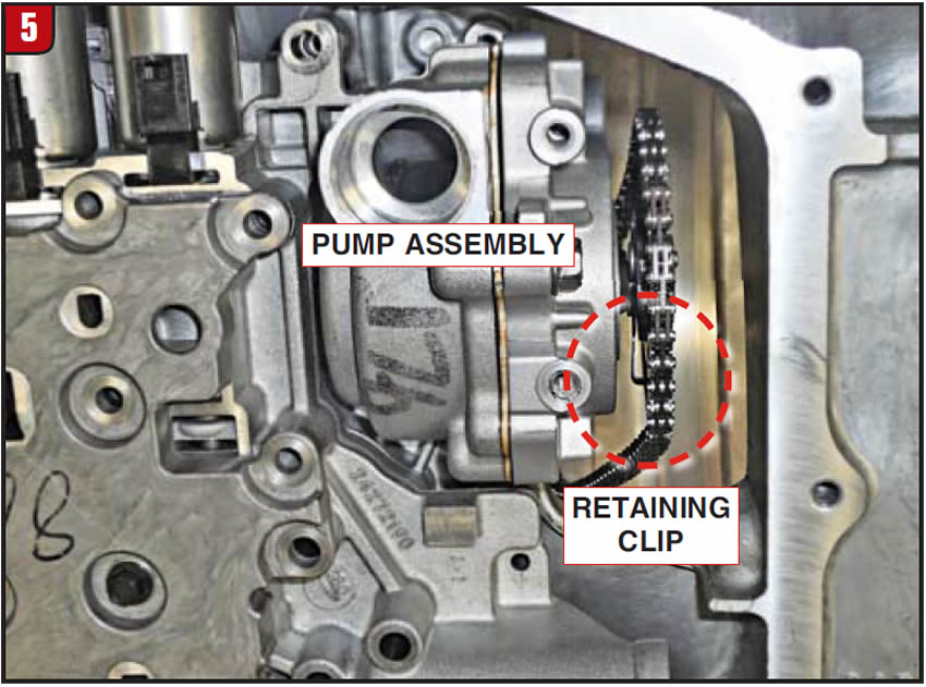
The plastic baffle is held to the valve-body assembly with two TTY (torque to yield) bolts that use a Torx Plus socket. The baffle is also made with torque-limit inserts. All TTY bolts used in the 8L90 should be replaced. With the baffle out of the way, the pump-driven gear and chain are visible and can now be removed. There is a hold-down clip on the back side of the gear that locks into the pump shaft groove. The clip has a bent tab that must be moved rearward out of the gear so that the clip can be pulled away from the shaft (Figure 5).
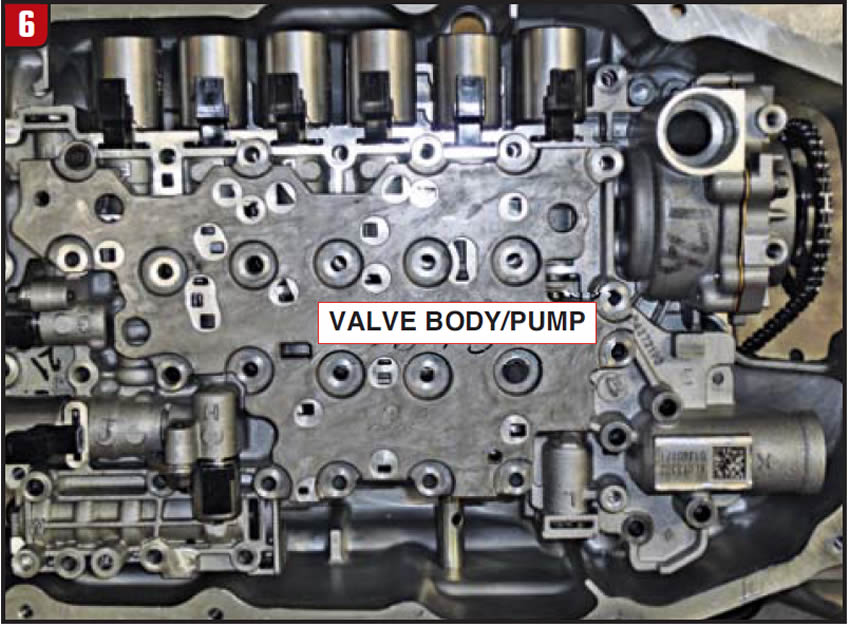
With the clip out of the way, the driven gear and chain can be removed along with the stator support. At this point it would make sense to remove all electrical harnesses as well as the valve body (Figure 6).
1-3-5-6-7 Clutch Assembly
The first of the three rotating clutches is directly behind the stator support. All three rotating clutches are positioned in front of the planetary gear sets to cut down on drag. The name of the clutch assembly is the 1-3-5-6-7, which coincidentally is applied in those gears. The housing is splined to the input shaft, which can be removed. The input shaft has four sealing rings in front of the housing and three sealing rings behind. The ISS sensor ring is pressed onto the housing and the clutch stack up is fairly straightforward (Figure 7). The apply piston is aluminum and uses a coil-type return spring and has a steel non-bonded balance retainer.
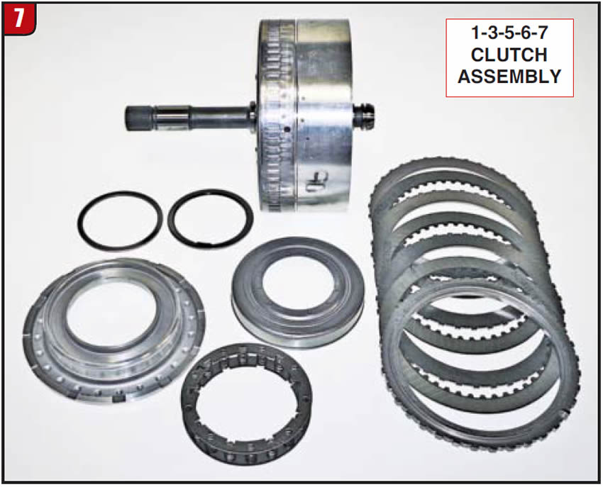
There are four frictions and steels but no wave spring, and the backing plate has a locating tab to prevent snap ring rotation. GM recommends a rather involved clutch-clearance checking procedure that requires a fairly expensive adapter tool that will preload the clutch packs to 80 pounds of pressure. The aftermarket may take exception to that process and do it differently. However done, proper clutch clearance must be set. Between the stator support and clutch housing is a large thrust bearing and selective spacer that is used to set unit endplay.
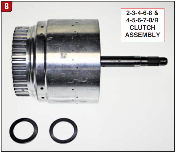
2-3-4-6-8 & 4-5-6-7-8/R Clutch Assemblies
The next two rotating clutch packs are contained in one housing and are a bit more complicated than the first clutch assembly. There is a bearing and race between the two clutch housings and the rear housing contains the intermediate shaft, (Figure 8). The hub for the 1-3-5-6-7 clutch is cut into the front of the rear housing. The two clutch assemblies are the 2-3-4-6-8 (small diameter) and the 4-5-6-7-8/R (large diameter).
The clutch stack up in this assembly is somewhat similar to the 6L80 1-2-3-4 & 3-5/R clutch drum layout (Figure 9).
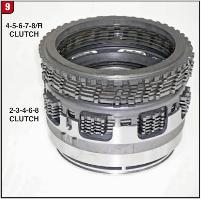
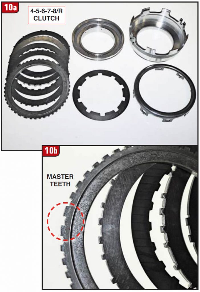
The larger piston that is forward in the housing actually applies the larger rearward clutch pack by using a tall apply ring. The smaller forward clutch pack is sandwiched in between. The 4-5-6-7-8/R is somewhat basic in design, but does have a few wrinkles. The apply components are aluminum with removable seals and the piston is installed into the housing first. The piston does have lineup tabs to prevent rotation and must be aligned correctly in the housing. The stationary aluminum retainer sets on top of the piston with the Belleville spring in between (Figure 10A). Make sure to install the return spring correctly. The clutch pack itself is also directional due to having master teeth that must be positioned correctly in the housing (Figure 10B). Ensure that the clutch-pack snap-ring opening is positioned with the master spline in the housing or it will not seat correctly.
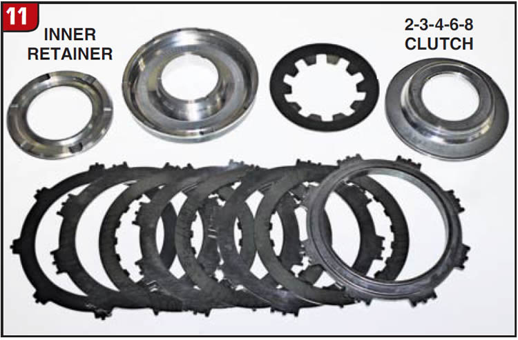
Although the 2-3-4-6-8 clutch pack has no master teeth, the piston apply set can be a little tricky. All apply components are also aluminum with removable seals, so make sure that all are installed. The first item to be installed into the housing is the inner retainer that could be flipped upside down. Notches cut into the retainer must face upward (Figure 11). The apply piston is then installed along with the Belleville return spring and balance retainer. As with the other clutch pack, make sure to install the snap ring correctly aligning the master spline.
Both clutch packs have wave springs that must be compressed to check clearance, if done the OE way. If not, merely factor in the spring thickness while checking clearance. Properly air check each apply port in the housing to identify any possible leak.
1-2-7-8/R Stationary Brake
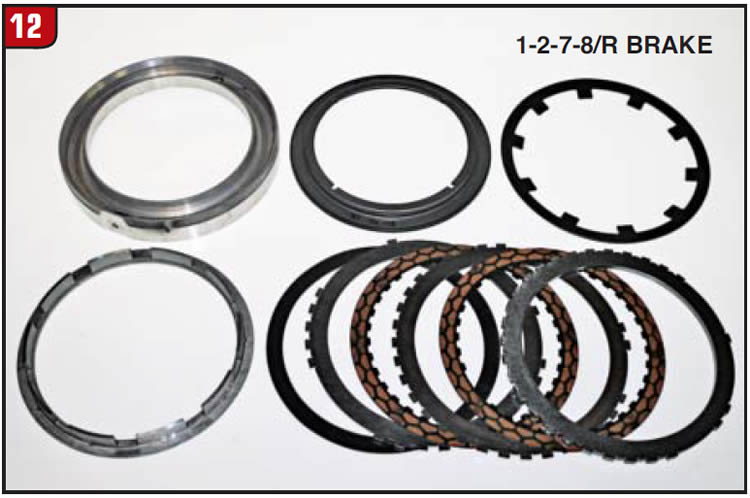
Both stationary brakes are positioned toward the back of the case and are independent of each other. The front stationary brake is the 1-2-7-8/R assembly, which is held in place with a snap ring. Before removing the piston housing, the valve body to case seal must be removed because it presses against the housing. There will be tension against the snap ring from the piston return spring, therefore a press will be needed to remove and install the assembly. With the snap ring removed, note the position of the housing locating tab and oil apply hole. The housing does contain a bleed orifice, which must be open. The piston is a bonded rubber design and will press into the housing easily. The piston return spring is also a Belleville design and locates against the case lugs when installed correctly (Figure 12). There is an apply ring that goes between the piston and wave plate with notches for the return spring fingers. The apply plate, steels and backing plate can only be installed in one direction. The friction plates are a segmented design. Use an adequate means for checking clutch clearance.
1-2-3-4-5/R Stationary Brake
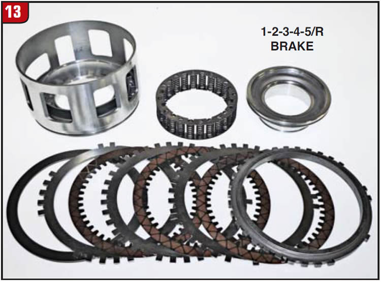
The remaining stationary brake is toward the back of the case and the clutch pack is removed through the front. After removing the retaining ring, the backing plate, frictions and steels, apply plate and wave plate can be removed. Unlike other transmissions that have the apply piston deep down in the case, requiring 4-foot-long arms, the 8L90 apply piston is removed with the extension housing (Figure 13). The piston is a tall design and has a locating tab that fits into the extension housing. The piston is held in position by an aluminum retainer and has a coil type return spring in between. Ensure that all seals are replaced. The frictions are also the segmented design and clearance must be checked correctly.
Special thanks to the folks at TransTec for providing the 8L90 unit used for illustration purposes.


