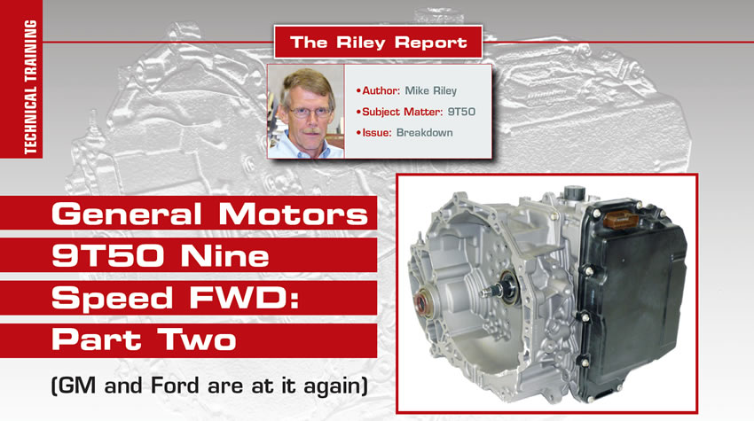
Riley Report
- Author: Mike Riley
- Subject Matter: 9T50
- Issue: Breakdown
(GM and Ford are at it again)
Rotating Clutches – The two remaining clutch packs in the 9T50 are almost a carbon copy of the two rotating clutches used by the 6T40. The clutch names for the six speeds of course are the 4-5-6 and the 3-5 / Rev. The 9T50 clutch packs were renamed 6-7-8-9 and 5-7/ Rev, although they operate the same.
Planetary Gear Sets – Another substantial change to the 9T50 has to do with one of the three planetary gear sets, disregarding the final drive carrier, which is also a planetary design. During disassembly, the first two planet sets in the stack up are the output and input planets. Not only do both planets look like their six speed counterparts, they basically operate the same as well. The change has to do with planet set number three which is the reaction planetary in the 6T40. That planetary is a simple planet design having one sun gear, one ring gear and one set of planet pinions. The planetary in the 9T50 number three position is more like a compound planet design having one large and one small sun gear, one ring gear and planet pinions that have a large and small gear connected together, (Figure 13). GM considers the planetary to be an overdrive/reaction planet. The carrier is either held stationary by the SOWC, connects to the large OD sun gear via the 4th clutch or is driven by the 6-9 clutch.


Unlike most other planetaries the OD/reaction carrier is bolted together and can be easily disassembled, (Figure 14). Items like pinion gear thrust washers, center thrust bearing, caged needle bearings and pinion pins as well as the aluminum clutch hub can all be replaced if only the stuff becomes available separately.
The remaining part of the OD/reaction planetary set has to do with the sun gear arrangement. In the 6T40 the reaction sun gear is welded to the shell that splines to the 2/6 stationary brake and to the 3-5/REV clutch assembly. The 9T50 design has both a large and small sun gear like any compound planetary set would, (Figure 15). The illustration shows the small sun gear above the large sun gear due to an extended shaft on the bottom shell. As stated previously, the large sun gear flange splines to and is driven by the 4th clutch assembly internally but is held stationary externally by the 2/9 stationary brake.
Those are the additional components that help to make this transmission a nine speed.
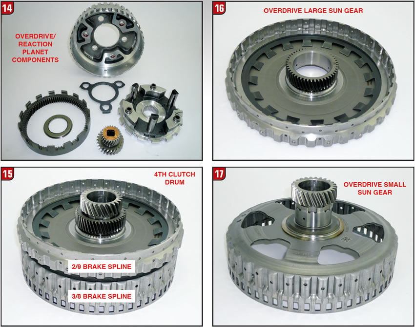
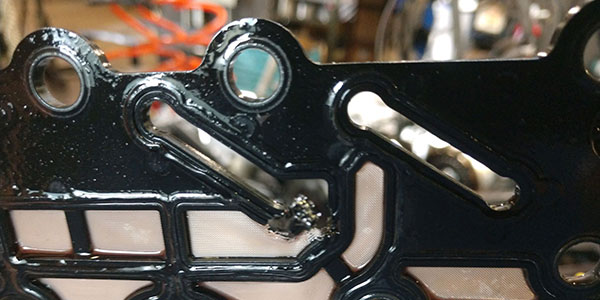
The large sun gear flange and 4th clutch drum are splined together with a Belleville return spring in between and a snap ring on the backside of the drum for assembly, (Figure 16). The large sun gear flange back and forth movement is limited to overall gear train end play whereas the drum itself can move forward or backward approximately 1/8” during apply and release of the 4th clutch which accounts for some of the clutch clearance.
Lastly, it is the small sun gear that connects to the clutch shell that is common with the 6T40, only in the nine speed transmission the shell has the extended shaft with notches at the end to accommodate the corresponding notches in the small sun gear, (Figure 17). Like in six speed models the shell/small sun gear can be driven by a rotating clutch (5-7/Rev) or held by a stationary brake (3/8). There is a thrust bearing that goes between both sun gear assemblies as well as the required bushings.
There is a dimensional difference between the two bushings that press into the 3/8 shell.
Solenoid/Valve Bodies – With the valve body cover removed all of the internal goodies are exposed that control transmission operation. Like other FWD units of this type there is a long plastic fluid level gauge that must be removed. The gauge retains fluid in the side cover area while hot and allows it to drain back into the case area once the unit cools down. All things considered, the valve body area is not bad to deal with.
The first item to look at is the solenoid connector harness and electrical plug, (Figure 18). There is no shortage of pins in the electrical plug, which is why it could be used in the space shuttle. There are a lot of harness connectors and caution should be used during removal and close attention paid during assembly. One other concern involves the hold down plate because directly underneath are two small solenoid accumulator valves and springs that can be easily lost.
The first chunk of aluminum is the solenoid body, which not only contains 10 solenoids but a fair amount of valves, sleeves and springs, (Figure 19). There are four basic styles of solenoids and they do have production part numbers etched into the bodies however, it is advisable to mark each solenoid and return them to the original position, if possible. Currently, the solenoids are not available separately.
The top four solenoids in the illustration are linear and have part number 24268036 etched into the bodies. The noses of the solenoids are short and metal. The bottom side of the solenoid body contains the remaining six solenoids, two of which are the simple on-off type with part number 24278294. As with most on-off solenoids the resistance value is noticeably higher than linear or PWM designs, in this case approximately 19 OHM’s.
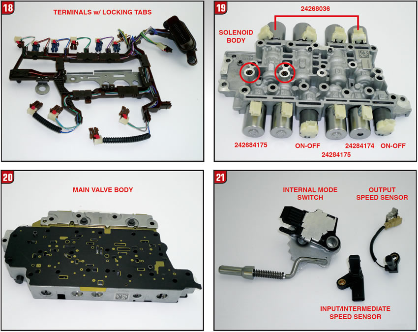
At first glance the last four solenoids appear to be the same, but they’re not. One of the four is slightly different but the good news is it’s easy to differentiate from the other three. Aside from the part number which is 24284174 the nose of the solenoid is black plastic. The other three solenoids which are the same are white plastic with part number 24284175. Hopefully at some point all solenoids would be available.
The valve body itself is pretty basic and could almost be mistaken for a six speed valve body, (Figure 20). The body contains a normal amount of valve trains and of course both separator plates have the gaskets bonded to them. At least the separator plates are available separately from the dealer. The solenoid body to valve body separator plate part number is 24288511 and the VB to case plate number is 24293402.
Switches/Sensors – The remaining electrical components are fairly standard especially when comparing them to previous six speed models, (Figure 21). The manual lever shaft is connected to a typical IMS (internal mode switch). There is a temp sensor connected to the solenoid harness assembly and there is an output speed sensor under the valve body and bolted to the case just like the 6T40.
What is somewhat uncommon is the input speed sensor that bolts to the end of the case. That sensor used on a six-speed transmission is just an ISS. The 9T50 sensor is a bit more because it is not only an ISS but it is also an intermediate sensor all in one. The input part of the sensor reads the signal from the reluctor at the end of the 5-7/Rev clutch assembly and the intermediate part of the sensor reads the 3/8 clutch shell.
What will they think of next?
Special thanks to the folks at Transtar Industries for providing the 9T50 used in this article and for their assistance.