Up to Standards
- Subject: Understanding electronic shift functions
- Unit: New Venture Gear transfer cases
- Essential Reading: Rebuilder, Diagnostician
- Author: Mike Weinberg, Rockland Standard Gear, Contributing Editor
The huge growth of sport/utility vehicles and the addition of four-wheel drive or all-wheel drive to many models of passenger cars has made the transfer case a major repair item for our industry. The ability to earn profits on these repairs is directly proportional to the technician’s understanding of the theory of operation and the ability to diagnose these units.
Transfer cases have become quite sophisticated, and many designs have extensive diagnostic routines. From what we see on tech-line calls and in helping customers resolve field problems, there is a great lack of information and understanding at the shop level. This article is devoted to understanding the electronic shift functions of the New Venture Gear transfer cases.
To begin, we must break down the different types of transfer cases into groups to make identification and diagnosis simpler. We start with two main groups and then divide those further into subgroups. The two main groups are four-wheel-drive (4WD) and all-wheel-drive (AWD).
4WD transfer cases, by definition, are those units that the driver can control, either mechanically, electronically or by computer. The driver can shift among different modes and ranges at will.
AWD transfer cases provide power to both axles without any driver control. Sometimes called full-time 4WD, these transfer cases have no driver-operated controls and use a viscous coupling or planetary differential to split power between the axles.
There are three divisions within 4WD: mechanical-shift, electric-shift, and automatic or active transfer cases. Late-model mechanical-shift units include the NV231, 241, 242, 261 and 271. All these units are shifted by a driver-actuated shift lever that permits the driver to shift between 2WD and 4WD modes and choose among 4WD ranges of 4W high, neutral and 4W low. Electronically shifted transfer cases permit the driver to choose among modes and ranges by pressing a dash- or console-mounted electric switch that engages an electric motor/encoder, which completes the shift requested. New Venture models include the NV233, 243, 263 and 273. A closer look at the design shows that an NV233 is a 231 with electric shift, a 243 is a 241 with electric shift, a 263 is a 261 with electric shift, and a 273 is a 271 with electric shift.
With active or automatic transfer cases, the driver electronically shifts through the modes and ranges by means of a motor/encoder that shifts the transfer case and applies an internal clutch pack to split the power between the axles. These units have an “automatic mode” for 4WD in which the transfer-case control module (TCCM) automatically sends power to the axle that needs it without any input from the driver. The computer reads prop-shaft and vehicle road speeds and, when they differ, will actuate the clutch pack until the shaft speeds are equalized. In the automatic mode this usually means that 95% of the torque is going to the rear axle until a slip is detected, and then the computer will send a pulse-width-modulated (PWM) signal to the encoder to apply as much torque as needed to the front axle. If the driver selected the 4W High range, the computer would lock the clutch pack to apply a 50/50 torque split to the axles with no modulation of the duty cycle.
In all the types of transfer cases the 4W Low range provides a gear reduction, usually in the range of 2.5-1, and this is suitable for off-road use only.
Before examining the motor/encoder technology, we need to correct some common misunderstandings and myths prevalent with your customers. The following will save you a lot of time and money:
- In any of the classes of 4WD transfer cases, it is NEVER all right to drive the vehicle in 4W High or 4W Low range on dry pavement. This will result in crow hop, high steering effort, wheel shake, internal transfer-case noise and popping, and – ultimately – internal damage. In snow, sand, mud, gravel, loose dirt or grass, there will always be some tire slip in the 4W High and 4W Low ranges. Dry-pavement operation causes internal components to bind because of spline lock, since there is no wheel slip. If your customer is driving on dry pavement in the 4W high or low range, fix the customer before he destroys the transfer case.
- All transfer cases are sensitive to variations in tire size and pressures. Begin every diagnostic routine by measuring the tire circumference with a stagger gauge or a tape measure. All tires must be within 1/4 inch in circumference. All tire pressures must be equal and correct for the rating of the vehicle. This simple beginning will eliminate at least 50% of your diagnostic concerns.
- All transfer cases are sensitive to fluid level and quality. All units that are run low on oil or use an incorrect oil will suffer damage quickly. Units that are run low on oil will overheat the drive chain immediately. The chain will stretch and damage the cases or the drive and driven sprockets. Any time you take a transfer case apart and find the chain with a light-brown baked-on color, the unit has been run low on oil. There is no accurate way to measure chain stretch, even on good units. During an overhaul, selling the customer a new chain is cheap insurance.
- The customer never understands mode and range shifts. A mode shift is a shift between 2WD and 4WD. A range shift is a change in the 4WD mode among 4H, N and 4L. It is never acceptable to make a range shift into 4W Low while moving. Most designs require the transmission to be in neutral or, with a manual transmission, the clutch pedal to be depressed and vehicle speed to be under 3 kilometers per hour. To access low range the design must mesh a sun gear to a splined shaft and activate a planetary gear set. This combination does not lend itself to shift on the fly.
Understanding the electronic shift motor/encoder begins with understanding its function. On electrically shifted transfer cases the motor/encoder will inform the TCCM of the transfer case’s present gear position. It will respond to driver commands to shift the unit within design parameters, and it will hold the transfer case in the selected gear until commanded to do otherwise. On active or automatic transfer cases it will provide the same function plus actuation of the internal clutch pack as commanded by the TCCM.
These are complex multifunction parts and are expensive. The motor itself is connected to multiple sets of internal planetary gears that can provide sufficient torque to make the shifts and apply the clutch pack. The encoder part of the motor is an internal position sensor that varies voltage to the computer to inform the computer of the transfer case’s gear position.
The most-important part of any diagnostic routine is to be aware of all the related systems that are involved in operating the transfer case. In many of these designs you will have an engine management computer, the TCCM, speed sensors (wheel and vehicle), transmission manual-lever-position (MLP) or range sensor, backup-light switch, the motor/encoder, and several body computers that integrate ABS, traction control and stability control.
Here’s an example of how easy it is to waste your day if you don’t understand the system:
A customer brings you an NV233 transfer case that will make a range shift into 4W Low in park at the driver’s command. This is not correct, as the output shaft of the transmission needs to be free to turn to help make the low-range shift. This shift should be possible only with the transmission in neutral (or with the manual-transmission clutch pedal fully depressed). The theory of operation follows:
In park, both the MLP and park/neutral switch are closed. When these contacts are closed there should be battery voltage at TCCM connector pin D2, and pin D16 should be grounded. This indicates to the TCCM that the unit is in park. In neutral, both pins D2 and D16 should show no voltage, informing the TCCM that the transmission is in neutral. In any gear the TCCM should see zero voltage on pin D2 and battery voltage on pin D16. Note: An open in circuit 75 or a blown turn-signal/backup-lamp fuse will cause the same condition. A misadjusted MLP can prevent a range shift in neutral.
Everything on those circuits is OK, so what is the cause of the problem? A backup-light-switch connector that is plugged in upside down will cause the park switch to have no voltage at pins D2 and D16. The TCCM then will allow a range shift in park, as it believes the transmission is in neutral. How many hours do you think it should take to solve a simple error like plugging in the reverse-light switch upside down? Assume nothing and take nothing for granted.
The encoder section of the motor is a four-channel switch. It consists of an inner ground ring that contacts a three-legged wiper arm. The legs are spaced 120° apart and make contact with the four conductive areas of the channels: A, B, C and P. Any contact by the wiper arm with voltage at one of the channels allows the circuit to complete to the inner ground ring and informs the TCCM of the position of the motor. Figure 1 shows the positions and the voltage readings you should see as the motor sweeps. Always start by back-probing the TCCM connector pins for voltage, and then back-probe the motor pins. This will identify an open circuit or a problem at the motor/encoder.
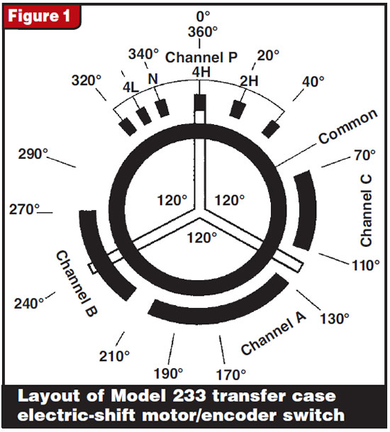
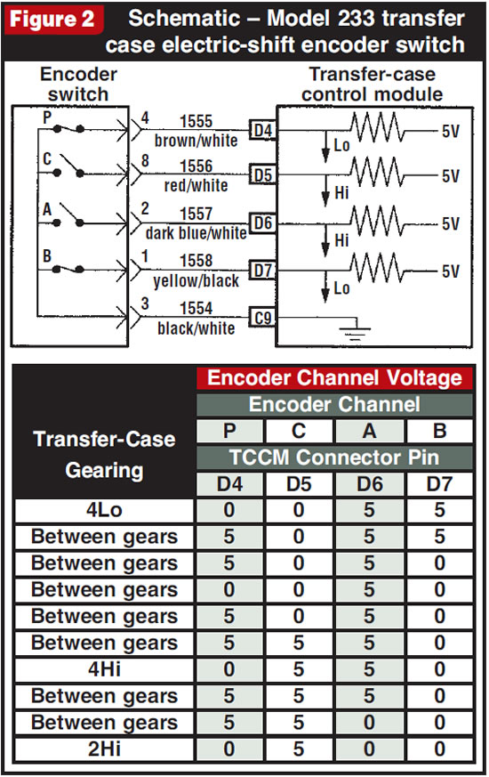
Figure 2 provides a schematic of the encoder switch and the correct voltage readings at the TCCM connector pins in each gear position.
The encoder section of the motor on the active transfer cases is more complex, because it has to apply the clutch pack at the correct duty cycle and shift and lock the motor to the correct gear. Figure 3, showing motor/encoder operation for an NV 136 transfer case, also applies to the NV246, except that the 246 has two relays instead of one. The motor side of the encoder consists of the same four-channel, 5-volt system as the NV233, but we will now review the clutch-apply side.
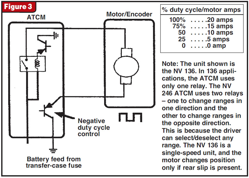
To apply the clutch pack at the desired duty cycle, the TCCM will energize a relay on its circuit board, sending 12 volts to the motor. To regulate clutch apply the TCCM will pulse-width-modulate the ground side of the motor, controlling the amount of current flow the motor will see and controlling the amount of clamp load the shift fork applies to the clutch pack. This in turn regulates the amount of power and torque split to the prop shafts. The duty-cycle amperage will vary from 0 amps=0 clutch apply to 20 amps=100% clutch apply.
The TCCM determines slip by reading prop-shaft speeds through a set of vehicle-speed sensors mounted on the transfer case. It makes continuous comparisons between the prop-shaft speeds and the vehicle road speed and decides by using a set of ratio comparisons how much duty cycle to apply to the clutch pack. At 0-10 mph a slip must be above 25 rpm before the TCCM takes action. The greater the road speed, the larger the amount of slip must be for the clutch pack to be applied. These units are capable of applying 100% duty cycle within 72 milliseconds (0.072 second) and can revert to zero duty cycle within 48 milliseconds.
This is why tire size and pressures are so critical in your diagnosis. If tire circumferences vary by more than 1/4 inch, the computer will see that as a slip and set a code or activate the system incorrectly. All the tires’ having the same side-wall labels doesn’t mean a thing. Only an accurate measurement will keep you from wasting valuable time and labor resources.