Leeward Tech
- Author: Ed Lee
- Subject Matter: Making the right choices for extreme stator repair
- Issue: Obey rules of repair
When you are rebuilding a late model converter it is very important to have the correct stator, impeller and turbine. The computers in today’s vehicles are sophisticated enough to pick up small changes in the stall or stall torque ratio in a converter. If a change is detected by the computer it will set a code.
Many of the late-model converters are popular enough to have an ample supply of replacement repair parts. But, as applications change, even a popular-model converter can have a new version that has a stator with a slightly different vane count or angle. These newer versions are often rare enough to make finding replacement parts a real challenge.
There was a time when a rebuilder could convert a high-stall stator to a lower stall by machining 0.125” off of the impeller side of the stator. This will still work on older vehicles, but in today’s world it is often necessary to repair the converter that you have to get the vehicle out of your shop.
The most common areas on a stator that need repair are the areas where the bearings ride. Bearing failures cause many of the problems, but wear to the bearing piloting surfaces create an equal number of the issues. When the problems occur on the removable stator cap on a stator the issues are minimal. Replacement stator caps and bearings are the first items that the aftermarket supplies make available. Many of the replacement stator caps come in the form of a bearing adapter and are equipped with an enhanced bearing.
When the issues involve the fixed side of the stator, they are a lot more serious.

Qualify
The first thing that you need to decide is if the repair is possible. If the stator is made out of magnesium the answer is quite often “NO.” The magnesium stators are lighter and most often carry a magnesium insignia (Figure 1).
If you are in doubt, trim a small sliver from your stator with a deburring tool or pocketknife and expose it to an open flame. Aluminum will not burn, but magnesium will burn white hot. If your stator is aluminum you may proceed.
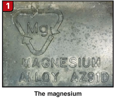
If you are using an OE (original equipment) bearing it may be necessary to build up the original piloting area with a TIG weld and aluminum filler wire. Once the area is replenished it can be machined back to original specifications. If the choice is to use an enhanced bearing, it may be possible to machine a new bearing piloting area without having to build up the area. The Chrysler bearing CH-N-1 (TW-2-4) is the overwhelming choice for use with a bearing adapter and is a good choice for an upgrade.
If the piloting pocket for the CH-N-1 (TW-2-4) bearing will not clean up the worn area on your stator, the CH-N-2 (TW-2-22) bearing, which is slightly larger in diameter, may work.
If the CH-N-2 (TW-2-22) bearing is still not large enough, there is a Mercedes bearing MB-N-2 (HW-2-2) bearing that is slightly larger (Figure 2).
Remember to always make certain that the mating surface for your replacement bearing supports at least ¾ of the length of the roller.
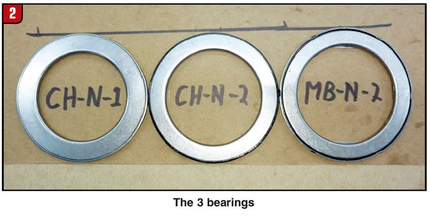
In some cases the bearing area is damaged beyond repair. The 4L80 converter that the roller clutch inner race has worn through the stator is a good example. For that converter, a replacement stator cap was the inspiration for a weld in repair piece.
If your stator requires this extreme of a repair, you have several possible choices (figures 3 and 4):
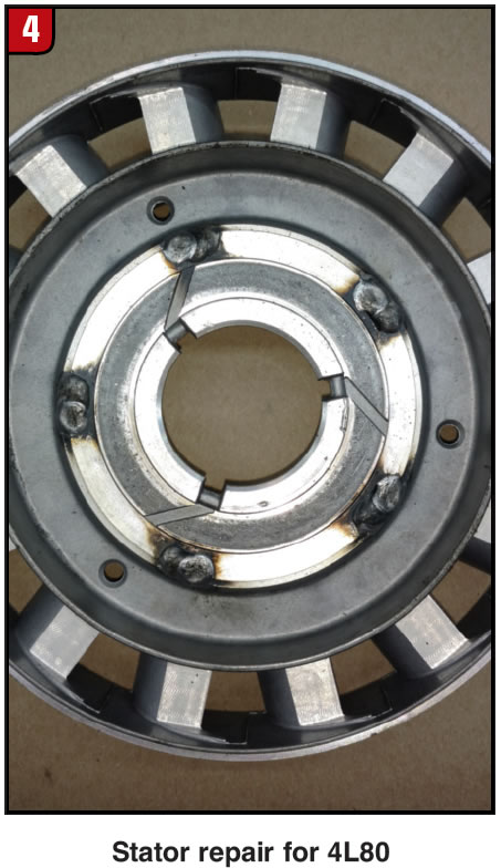
- 1) Trim down an existing replacement stator cap to weld into your stator.
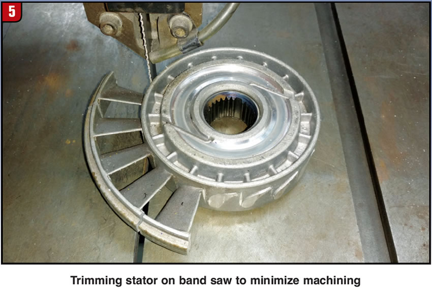
- 2) Cut a repair piece from a common stator or like stator that is damaged in another area. Trimming the stator inward to the one-way clutch outer race with a band saw will lessen your machine work.
- 3) Machine a repair piece from billet stock material (Figure 5).
Rules for extreme stator repair
- 1) In each case you will need to have your repair piece rest on the one-way clutch outer race. This will keep the repair piece perpendicular to the centerline of the stator.
- 2) Make the repair piece a slight press fit into the stator. This will keep it on the proper centerline.
- 3) Securing the repair piece to the stator can be done with a small stitch weld. It will not be necessary to weld the complete circumference of the repair piece because there are no rotating forces acting on this piece. To help to prevent any distortion issues, you may want to have the one-way clutch inner race secured in the stator by the removable stator cap. You may choose to do the finishing machine work to the bearing surface after the repair piece is welded in.
- 4) Last, but not least, your stator cap needs to have passageways for oil to pass from the ID (inside diameter) to the OD (outside diameter) of the bearing. Remember that one of the entrance/exit paths for the converter lives on the ID side of the bearing and the other entrance/exit path lives on the OD side of the bearing. 30 to 32 gpm (gallons per minute) needs to pass through this area or the converter will over heat. Drilling holes through the cap under the bearing is the best way to get the flow you need, but grooves will work as long as they still provide proper support for the bearing.
Resurrecting a stator may be a daunting task, but it may be the only solution.


