Upgrading the Honda Impeller-to-Stator Bearing - Transmission Digest

Upgrading the Honda Impeller-to-Stator Bearing

Torque-converter rebuilders have been reporting Honda bearing failures in increasing numbers. The bearing failures have been from different locations within the converters and have been reported in most of the Honda and Acura models. The most common of the failures has been the bearing between the impeller and stator in the larger-diameter converters. In all converters, the bearing in this location carries most of the thrust load when the vehicle is accelerating, and it is typically the first bearing to fail. Because the larger-diameter converters are used in the larger, higher-torque V-6 applications, the thrust loads on this bearing are even greater.

Upgrading the Honda Impeller-to-Stator Bearing

Torque Converter Tech Tips

Subject: Bearing failures
Vehicle Application: Honda and Acura
Essential Reading: Rebuilder, Diagnostician
Author: Ed Lee

Torque Converter Tech Tips

  • Subject: Bearing failures
  • Vehicle Application: Honda and Acura
  • Essential Reading: Rebuilder, Diagnostician
  • Author: Ed Lee

Torque-converter rebuilders have been reporting Honda bearing failures in increasing numbers. The bearing failures have been from different locations within the converters and have been reported in most of the Honda and Acura models. The most common of the failures has been the bearing between the impeller and stator in the larger-diameter converters. In all converters, the bearing in this location carries most of the thrust load when the vehicle is accelerating, and it is typically the first bearing to fail. Because the larger-diameter converters are used in the larger, higher-torque V-6 applications, the thrust loads on this bearing are even greater.

A root-cause analysis completed on the failed bearings found that although the thrust load on the bearings was a factor, it was not the primary cause of the bearing failures.

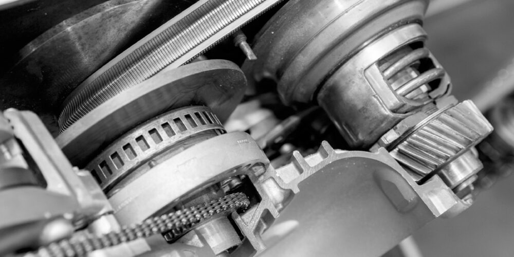
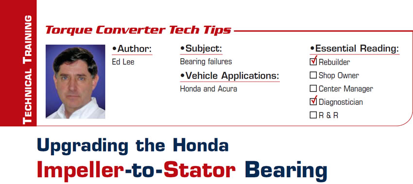
The OE Honda bearing for this application is an open-faced bearing that uses the thrust surface of the flanged impeller hub as one of its bearing races. The impeller hub in Figure 1 is typical of a failed unit.

A close inspection of the impeller hub in the failed converter yielded several clues about the failure. The obvious discoloration caused by overheating was the first clue. The potato-chip wear pattern was a second clue, and the wear pattern that extended the entire length of the circumference was a third clue.

Since the Honda converters are well known for their overheating issues, it would have been easy to jump to the conclusion that the converter overheating took the temper out of the bearing surface of the impeller hub and caused the bearing failure. Converters that have overheated enough to turn blue have been hot enough to alter the temper of the metal. A check of the hardness of this surface seemed to back up this assumption. The normal hardness of a bearing race should be in the 58-60 Rockwell range, and the bearing surface of this impeller hub was as low as 50 Rockwell at one point.

Although the overheating issue remained a good candidate for causing the temper loss, it was not the only possibility. The hub in this unit was not the original but a replacement. Now the question became: Did the converter overheat enough to affect the replacement hub’s hardness, or was the temper taken out of the replacement hub’s bearing surface during the installation welding process? Testing the hardness of the bearing surface of the impeller hub before and after the weld process would be necessary to answer this question.

The bearing surface of a virgin replacement impeller hub was tested and fell within the 58-60 Rockwell range. The impeller hub was then welded into the impeller and the hardness was retested. Starting at the beginning of the weld and continuing about 75% of the duration of the weld, the hardness remained in the 58-60 Rockwell range.

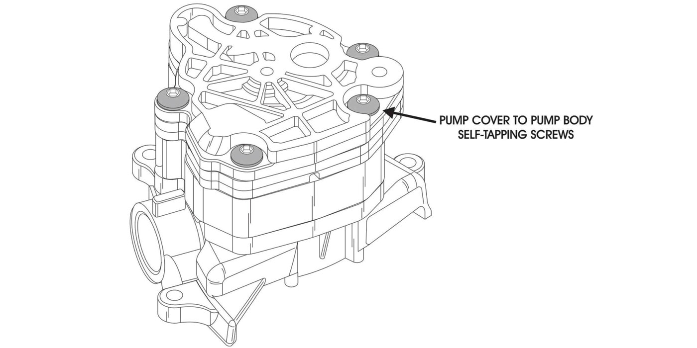
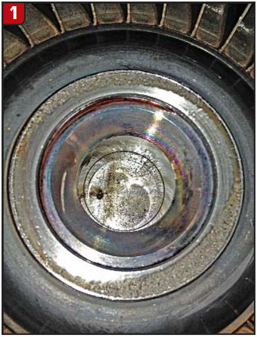
The hardness measured near the last 25% of the weld was a different story. In this area, the hardness varied by 10 Rockwell and at one point dipped as low as 50 Rockwell. The results of the second hardness test led to several conclusions. One was that the wear at the entire circumference of the bearing surface in Figure 1 was probably caused by the loss of temper during the weld process and that the potato-chip distortion also was caused by the same heat. A second conclusion was that Honda had recognized this issue and addressed it by using a two-headed welder to install all its impeller hubs (Figure 2).

The third conclusion was that it was time to either invest in a two-headed welder or source a suitable enclosed bearing to replace the Honda OE bearing. Since two-headed welders are quite expensive, the enclosed bearing seemed to be the better choice.

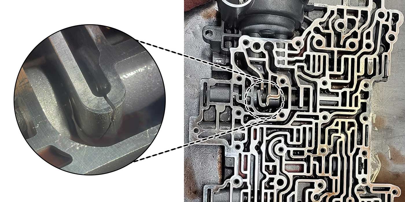
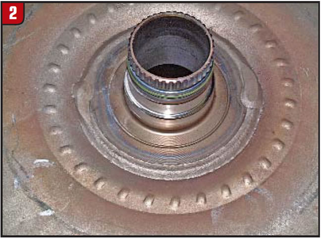
The bearing found between the stator and impeller in most RE5R05A converters (Figure 3) is a good replacement bearing.

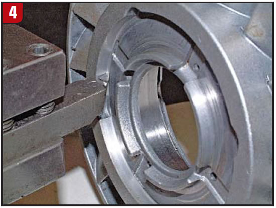
It is very robust, and dimensionally it is ideal for the application. It is 0.035 inch larger in diameter than the cavity where the OE bearing and wear plate live, so a minimal cleanup of the bore is all that is necessary to fit the bearing into the stator (Figure 4).

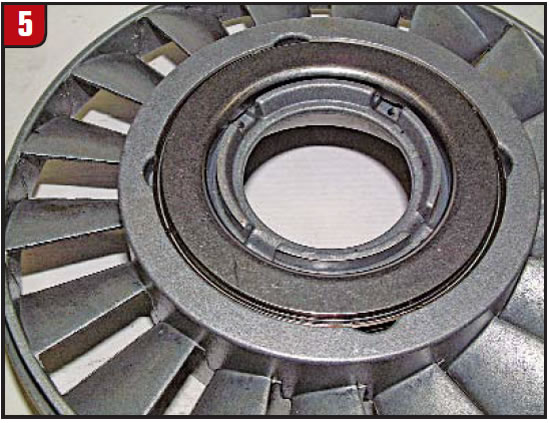
Continuing the machining process to the bottom of the bore also will provide plenty of lube oil for good bearing life. The finished product will look like Figure 5.

Another plus is that this bearing is about 0.040 inch thicker than the combined thickness of the OE bearing and wear plate. This extra thickness allows you to either clean up the wear on the OE impeller hub or remove the potato-chip distortion of the replacement hub caused by the welding process.

Ed Lee is a Sonnax technical specialist who writes on issues of interest to torque-converter rebuilders. Sonnax supports the Torque Converter Rebuilders Association. Learn more about the group at www.tcraonline.com.

©Sonnax2012

You May Also Like

Don’t fear customer complaints about CVTs

Continuously Variable Transmissions, or CVTs, are more common than you think. Audi, Subaru, Nissan, Ford, GM and many other automakers use CVT transmissions in cars and SUVs. There is no way to avoid them. Chances are there is one in your shop right now. What does CVT mean for technicians? On the maintenance side, a

CVT-Transmission-2

Continuously Variable Transmissions, or CVTs, are more common than you think. Audi, Subaru, Nissan, Ford, GM and many other automakers use CVT transmissions in cars and SUVs. There is no way to avoid them. Chances are there is one in your shop right now.

What does CVT mean for technicians? On the maintenance side, a CVT requires more or the same frequency of fluid and filter changes as a conventional automatic transmission, and many of the basic procedures are the same. On the diagnostic side, a CVT is less complicated internally than a six- or nine-speed transmission. Diagnostics with a scan tool are about the same. On the service side, while you may never pull a variator or belt out of a CVT, you can service components like sensors, pumps and valve bodies. The point here is not to fear a customer complaint about a CVT. 

Shift Pointers: A Chrysler 300 no-shift complaint

The case study has to do with a 2009 Chrysler 300 C 5.7L Nag1 RWD with 71,923 miles on it (see Figure 1, above). Related Articles – 2024 State of the Powertrain Industry – Powertrain industry directory and buyer’s guide 2024 – A guide to common GM, Ford and Nissan programming issues It is based

A guide to common GM, Ford and Nissan programming issues

One of the most common complaints I hear from shops when trying to install a new GM TCM is, “The module will not communicate.” While that might be partially true, by design they won’t communicate until they are programmed. If programming fails, there will be an “E” code set which will help you get to

Shift of the shaft: Diagnosing Chrysler 48RE manual shaft issues

The TorqueFlite transmission has been around since mid-to-late 1950s. There have been many changes surrounding the manual shaft and rooster comb through the years. This transmission shaft controls the position of the manual valve that directs oil for the gear ranges, but it also is used for a Reverse light control as well as Park/Neutral

Sometimes, a diagnostic code is all you need

With ATSG having the opportunity to help shops solve problems, sometimes we get faced with some real doozies. A shop will call and give us a laundry list of DTCs, leaving us to think someone must have a bulkhead connector unplugged. We then go through the arduous task of deciding which codes prompted other codes

Other Posts

Easy TH400, 4L80-E reverse servo setup: Craft your own tool

While not as sensitive as some shifting bands, the Reverse band adjustment on a TH400 or 4L80-E transmission is critical, and failure to get it right has tripped up even the best builders. There is nothing worse than getting the transmission installed, putting it in Reverse and then not going anywhere or having no engine

Spotting different 68RFE designs through the years to avoid issues

The Chrysler 68RFE has had several changes through the years. Its four-speed predecessor began with a noisy solenoid pack identified by a black colored pass-through case connector (seen in Figure 1).  Related Articles – Outgrowing the walls: The story of EVT Transmission Parts – Valve body and component suppliers: A comprehensive list – Shift Pointers:

Shift Pointers: Failures caused by incorrect tire sizes

For years ATSG has produced a wide range of issues related to improper tire sizes on vehicles. Even under-inflated tires have been known to cause issues. Problems such as premature failure with an active 4WD transfer case will occur with incorrect tire sizes. Related Articles – Understanding lube flow control valves in Toyota/Lexus UA/UB80 transmissions

Shift-Pointers-Jan-Figure-1-1400
Understanding lube flow control valves in Toyota/Lexus UA/UB80 transmissions

The Toyota/Lexus UA80 and UB80 transmissions first came out in 2017 in Highlanders and Siennas. The UA80 is used in V6 applications, and the UB80 is paired with four-cylinder versions. They have been called Toyota New Global Architecture type transmissions, and alternately referred to as the “Direct Shift 8AT” eight-speed automatic transmission. This transmission was

Tasc-Tip-December-Figure-1---LFC-Valve-OE-Partial-Circuit-Diagram-1400