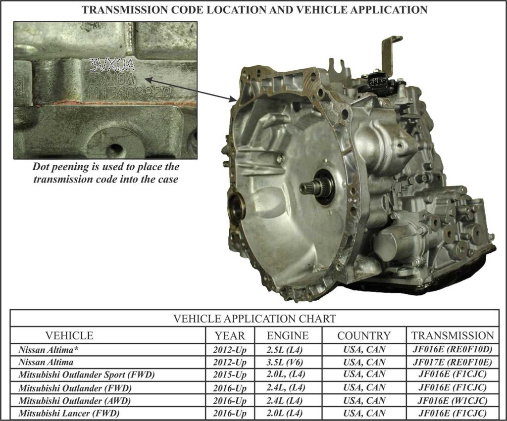
The Japanese Automatic Transmission Company produces a continuously variable transmission (CVT) known as the JF016/17E, which has been fitted behind 2.0L to 3.5L engines worldwide. Here in the United States, there is a light version called the CVT-8LT for 4 cylinder applications (JF016E) and a heavier version called the CVT-8HT for V-6 applications (JF017E). Nissan refers to these transmissions as the RE0F10D (Transmission Code 3VX0A) and the RE0F10E (Transmission Code 3WX0A). Mitsubishi uses the F1CJC designations for FWD applications and the W1JCJ for AWD applications (Figure 1).
One of the failsafe features that occurs when certain malfunctions take place is no throttle response, rendering the vehicle inoperative. We see this frequently with Nissan applications when such things are not right with the brake circuit or wheel speed signals. A slipping detection may also initiate a no-throttle response.
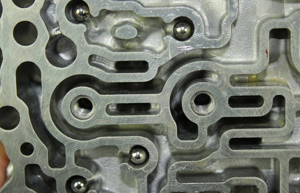
It is also possible to encounter a no-move condition which may be interpreted as a failsafe condition. Figure 2 provides a view of the valve body showing the solenoids it utilizes to operate this CVT.
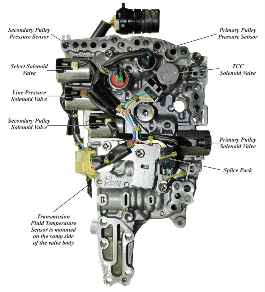
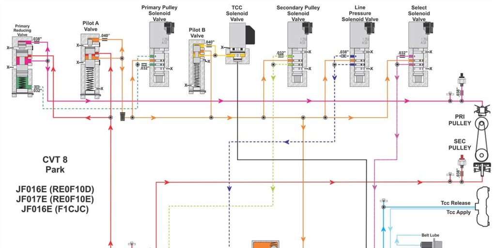
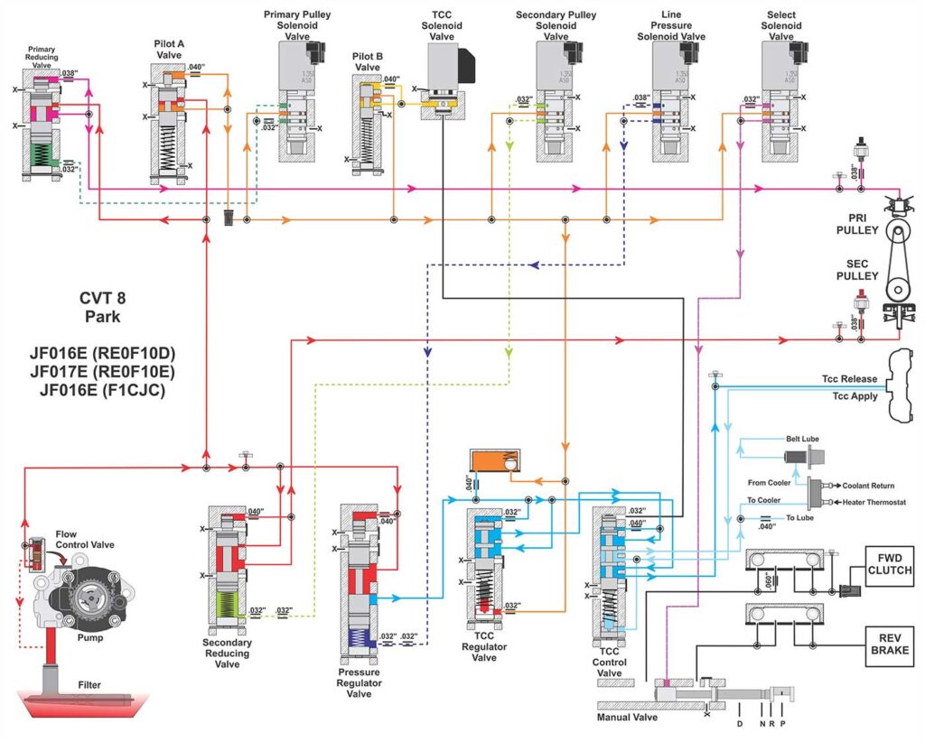
Figure 3 provides a complete hydraulic view of this type of transmission. If you look at the pressure supply to the manual valve, you can trace it back to the Select Solenoid.
With a further look at the Reverse and Drive Circuit from the Manual Valve, you will notice that there are two check-balls in each of these circuits going to their respective clutch. Figure 4 shows where these check-balls are in the valve body. The reason for the double check-ball is to control both the apply and the release of the circuit.
As you can see, JATCO went to great lengths in controlling the apply and release of the clutches to prevent harsh engagements which in turn may damage the pulley assembly. In fact, the early design of the CVT 2, otherwise known as the JF011E CVT, utilizes two solenoids in conjunction with two valves along with the double check-ball configuration per circuit to accomplish this task. The drawback with this design is that garage shifts into gear can take up to two to three seconds and are to be considered normal.
With the Select Solenoid controlling supply pressure to the manual valve, it has the ability to control garage shifts into gear. The TCM receives input from the throttle positions sensor, the brake sensor and the range sensor when the selector lever is moved into reverse or drive. It then monitors the time it takes for the input speed sensor to ramp down to 0 RPM. The computer can adjust the apply time of the applying clutch through the Select Solenoid (See figures 5 and 6).
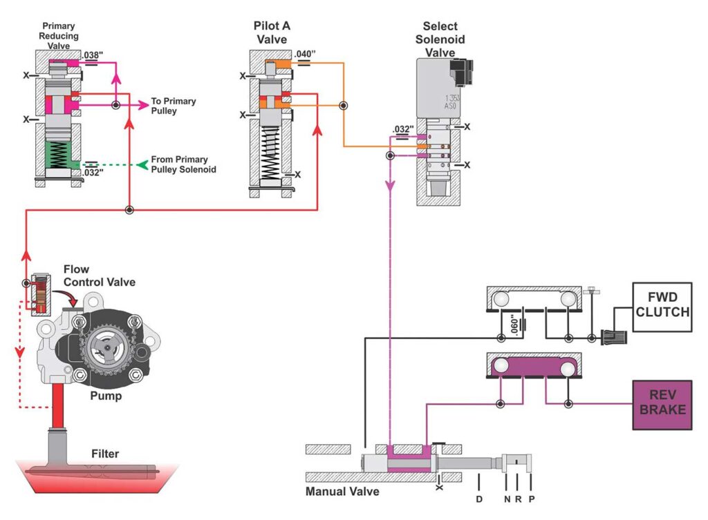
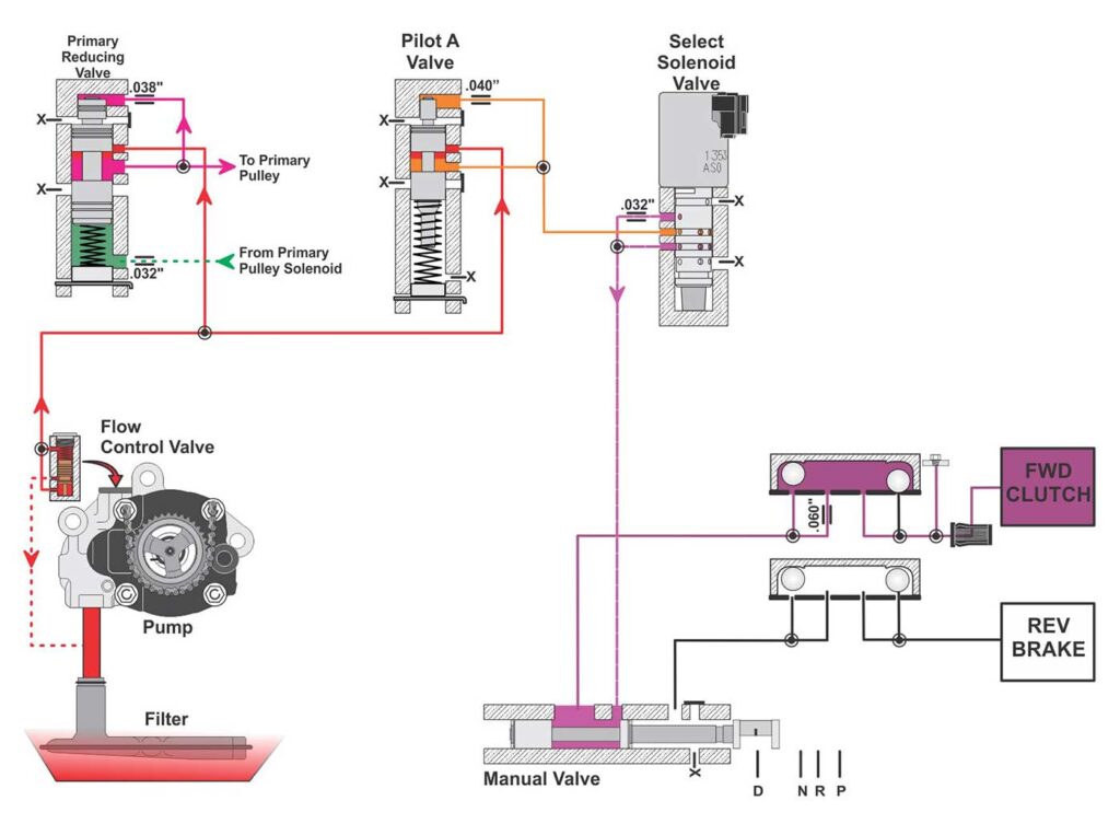
Nissan describes this process as follows: Based on accelerator pedal angle, engine speed, primary pulley speed, and the input speed, the optimum operating pressure is set to reduce impact of a selector lever operation while shifting from “N” (“P”) to “D” (“R”) Position. If it sees 0.3 to 0.4 seconds of engagement, a code P2813 will set with Nissan vehicles, typically for a mechanical failure of the solenoid. P2814 seems to set if there is an electrical problem while P2815 has been known to set for both a mechanical and/or electrical failure.
Depending on the way this solenoid fails mechanically, it could prevent all engagements, or allow for very harsh engagements. When the solenoid fails for harsh engagement, it could be due to a mechanically failed solenoid—but it could also be for another reason.
Read more columns from our Shift Pointers series here.
In one example of this, ATSG recently encountered on its technical help line a 2016 Mitsubishi RVR vehicle in Canada that exhibited a very harsh garage shift into gear. A DTC P2719 was set for “Abnormality in Select Pressure Solenoid Valve Function.” This is a performance code. If there were electrical issues, a code P2720 would set for low input, while 2721 would set for high input.
When reviewing data from a recorded movie, the tech observed that when this code 2719 set, PSI amperage dropped to 0 indicating max line pressure. The tech found this odd as the TCM noticed harsh engagements setting this code. Failsafe would be to adjust pressures to safeguard against damage and prevent throttle response. Throttle response was still functional and with PSI amperage going to 0, max pressure was present. This didn’t seem to fit the failsafe method of these CVTs.
The diagnostic routine for this code provided only two possible causes: the valve body assembly with solenoids, or a defective CVT. Since these options didn’t seem likely, further checks were made which included scoping solenoid signals. By doing this, it proved that a defective TCM was the cause, making sense of all these observations.