TASC Force Tips
- Subject: Valve-body testing methods
- Essential Reading: Rebuilder, Diagnostician
- Author: Bob Warnke
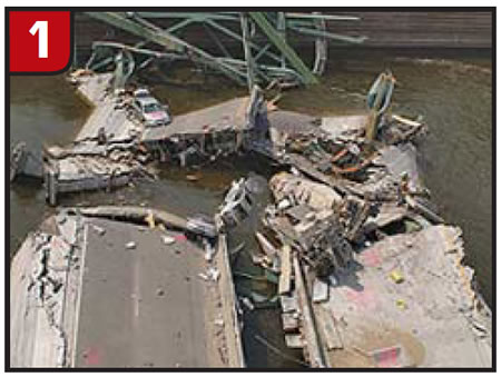
At the time of this writing, two parties are discussing a fiscal cliff. Party one proposes to leave the political stalemate as is and just wait and see what happens after we go over the edge. That perspective has been compared with repainting a trillion square feet of rusted bridge (Figure 1). The second party claims that there are alternatives to the stalemate and that the cliff can be avoided. Their view is to stop the traffic (i.e., programs and entitlements) until the bridge can be re-qualified so they can then decide whether it should be repaired or replaced. Then a question was asked: How did we get to this point?
This situation struck me as a perfect parallel to valve-body service. Politics aside, let’s review the evolution of valve-body testing and the state of current qualification practices.
Although traditional visual indicators such as the wiggle, deflection, flashlight and visual bore-wear inspection are still useful, we’ll start this review with pressure and vacuum before finishing up with valve-body test stands.
There are currently two procedures for air-pressure testing: the unregulated air gun and a calibrated air-test plate. The air-gun test originated as a clutch air-pressure test in transmission manuals before being adopted for valve-body testing. A visual leak with an air test is caused by excessive valve-to-bore or end-plug clearance. After air testing, the question becomes: What is normal or excessive leakage? Making the pass/fail decision properly requires experience, a downfall of this type of air test. Variables include the air supply, type of air tip, length of time to push out the fluid and noise level of the shop.
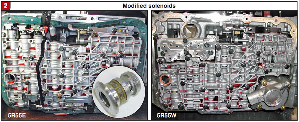
Moving along the valve-body testing timeline to another decade, we added fixtures to the air test to isolate circuits. Examples include modified EPC solenoids for the 4L60/80-E, 5R55E, 5R55W or F5A etc. Now a solenoid was modified and air directed to the EPC signal circuit while the unit was assembled. These were cost-effective methods and provided a visual indication of bore wear (Figure 2).
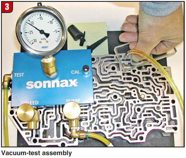
The next refinement in qualifying a casting was the use of vacuum testing, a technique derived from valve-guide/seat testing used in cylinder-head remanufacturing. A minimal drop in vacuum occurs when this test is applied to valve-to-bore clearance. Vacuum is obviously the opposite of a pressure test. Where air pressure will push fluid and contaminants out of the bore, vacuum pumps will pull it into gauges and orifices. This means that – for best results when vacuum testing – it’s critically important that the assembly be clean and dry. A routine calibration is performed to reduce contamination and also allow for variance in pump capacity. Unlike air testing, which hinges on a rebuilder’s personal experience, vacuum-test gauges produce specific data that make for an easier diagnostic learning curve.
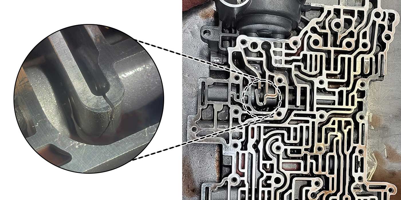
To perform a vacuum test, the rebuilder seals a circuit with a plate or pad (Figure 3), moving between circuits to test various areas. Once clean, an entire casting can be checked for valve-to-bore tolerance. Other benefits include the ability to remove valves from the bore, check boost-sleeve wear and the condition of solenoid seats etc.

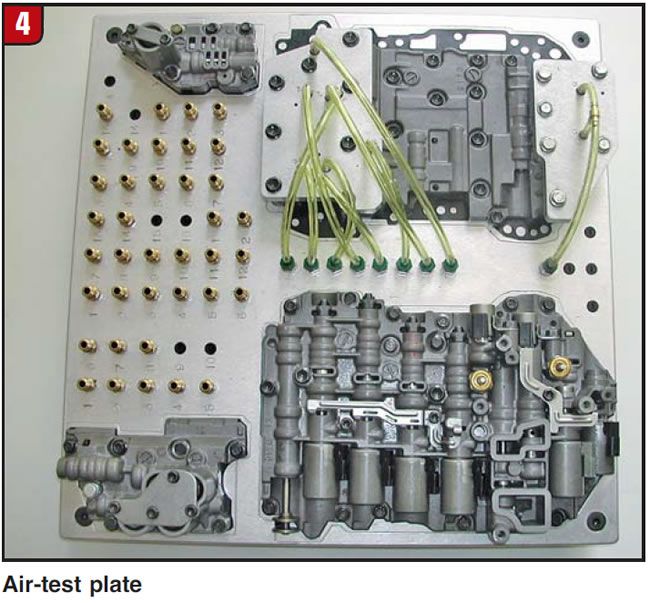
A valve-body air-test plate also uses air pressure, but pressure and volume are precisely regulated. In this test an assembled valve body is bolted to a plate that has multiple feed ports to each bore. An air-flow meter and a gauge (analog for visual or digital tied to a computer) record a pressure drop and flow increase. Generally a new or acceptable assembly is tested and used as the baseline. The greater the variance from a known-good measurement, the more clearance there is between the valve and bore. The instrumentation and regulators are used for all applications, but each type of valve body requires its own test plate (Figure 4). There are a few big advantages to this type of testing. Pre-cleaning and the labor involved in fastening and recording gauge equipment are eliminated. The cost to repair also can be estimated and service noted before opening it.
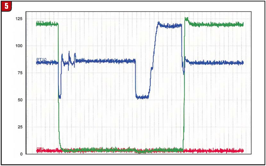
Next we come to the arrival of modern hydraulic valve-body test stands, or VBTs. Hardware and software advancement has been rapid to duplicate clutch-to-clutch and skip shifting. The key to testing a six- to eight-speed valve body or mechatronic unit is to command and record as if the transmission control module (TCM) were running it. This requires extensive solenoid manipulation and data acquisition (Figure 5), specifically the transition or X pattern of multiple solenoids from exhaust to fill. In the vintage VBT and on/off valve bodies, only end-of–the-line clutch pressure was monitored. The operator could control throttle pressure via cable and monitor minimum and maximum pressure, using feel as time.
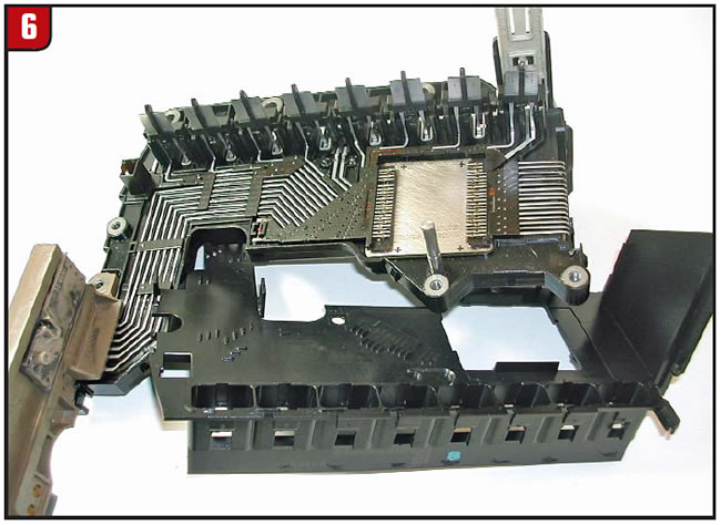
The newer TCMs, however, focus on time and flow rather than pressure (Figure 6). The VBT of today can test the solenoid output and run a six-speed shift cycle in two minutes, without operator involvement.
A valve-body test stand requires the addition of a specific plate just like air testing but has the benefit of including the control program, harness and cabinetry. The payback for this equipment is realized in volume and quality assurance. A remanufacturer understands that the VBT reduces R&R and rework from the dyno or vehicle.
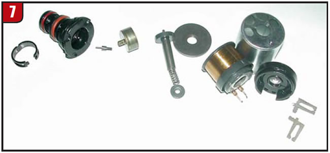
This brings us to the current state of transmissions, in which linear solenoids (Figure 7) are now the framework for clutch-to-clutch shifts. They receive a TCM output and convert it to a variable pressure. Because of heat, wear and contamination, the coil reaction and pressure degrade, forcing the TCM to adjust or adapt. Unlike a federal budget, though, TCM adaptation is not unlimited – it will set a code to stop things from going over the proverbial cliff – but because these solenoids are no longer on/off, they cannot be qualified with old diagnostic methods like air or fixed oil pressure. Similar to the valve body or mechatronic unit, they require testing in a severe environment that includes heat, pressure and cycle time.
Bob Warnke is a Sonnax vice president of technical development and a member of the TASC Force® (Technical Automotive Specialties Committee), a group of recognized industry technical specialists, transmission rebuilders and Sonnax Industries Inc. technicians.
© 2013 Sonnax Industries