Body of Evidence
- Subject: Identification of valve bodies and channel plates
- Unit: 4T65-E
- Vehicle Applications: GM, Volvo
- Essential Reading: Rebuilder, Shop Owner, Center Manager, Diagnostician, R & R
- Author: Jeff Parlee
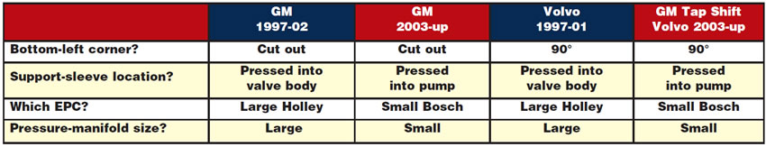
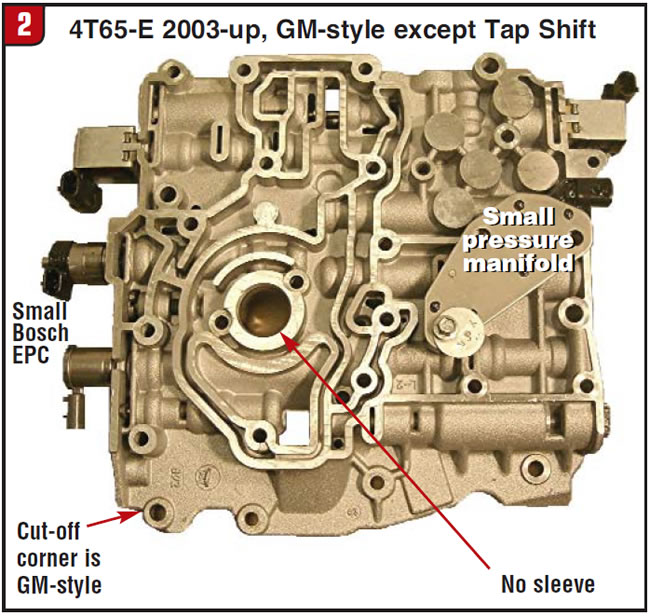
Let’s start with the valve body. Unfortunately, there are no casting numbers on the 4T65-E valve body for quick identification. The four most-common 4T65-E valve bodies are the early GM, late GM, early Volvo and late Volvo. There are more than four variations, and they can be found during the crossover years of 2002 and 2003. There are four questions that you need to answer to properly identify the valve body.
- Is the valve body a Volvo or GM type? The Volvo valve body will have a 90° corner at the bottom left (below the TCC solenoid). The GM valve body will have a cutout at the bottom-left corner.
- Is the support sleeve pressed into the valve body or the pump? Early valve bodies have the support sleeve pressed into the valve body. Late valve bodies have the support sleeve pressed into the pump.
- Which style of EPC solenoid is on the valve body? Early valve bodies use the large-diameter Holley solenoid. The late valve bodies use the small-diameter Bosch solenoid.
- Which pressure manifold is on the valve body? The early valve body will have the large pressure manifold to cover the six holes with the six pressure switches. The late valve body has the small pressure manifold, which has only one pressure switch; the other five holes are cast closed.
Use this chart and figures 1-4 to properly identify your valve body.
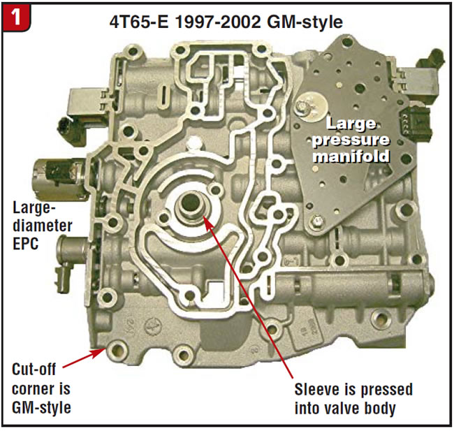
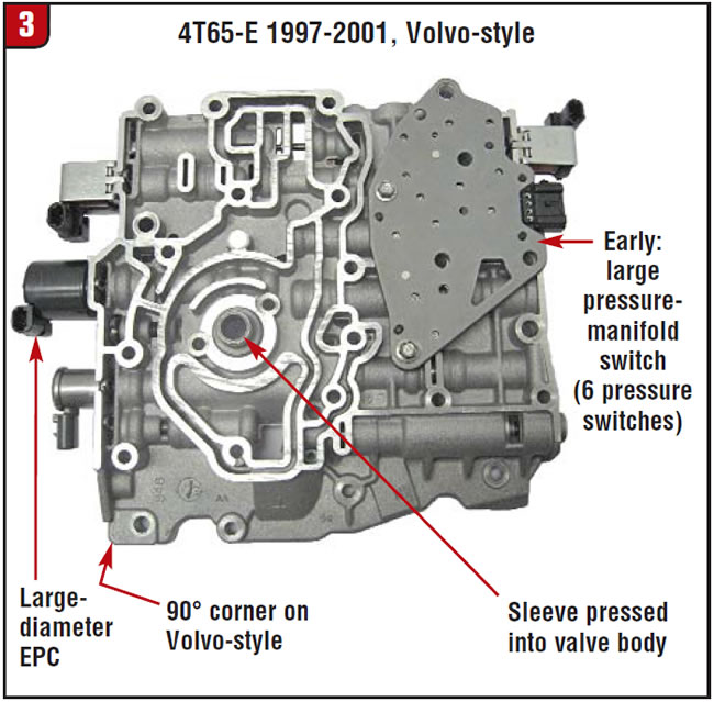
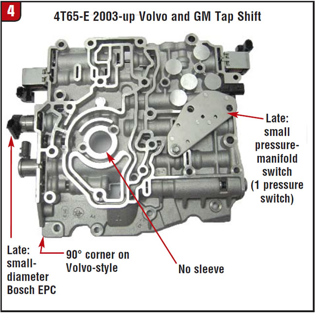
The GM Tap Shift valve body and channel plate are the same as in the late Volvo.
There are a variety of different 4T65-E channel plates. Some of the differences are:
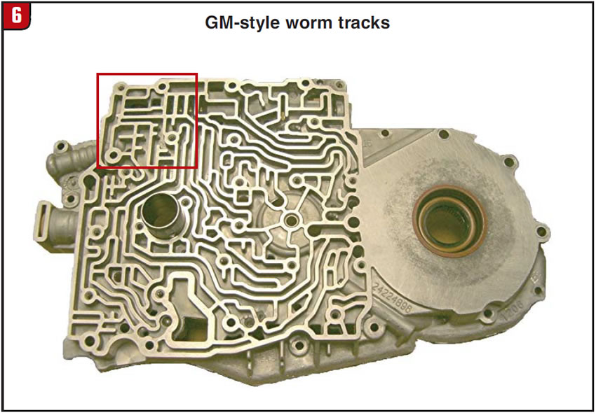
- GM- or Volvo-style worm-track configuration on the valve-body side.
- One or two blow-off balls and springs.
- Early (1997-2002) or late (mid-2002 & up).
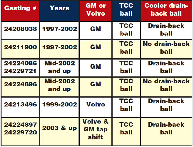
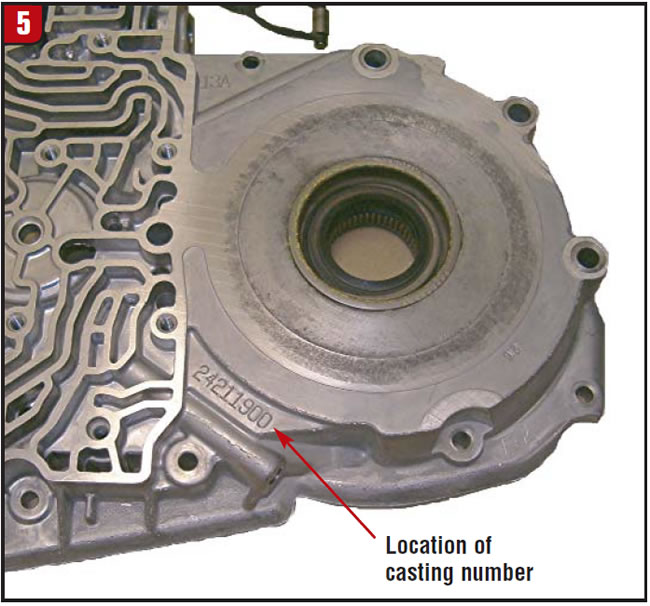
The channel plates have a casting number on the outside of the plate just below and left of the flat machined area where the axle seal is. Using the following chart will help to identify the channel plate. Be aware that it is easy to remove or install the cooler blow-off ball, spring and retainer. Therefore, the blow-off-ball configuration may not match the description on the chart.

GM or Volvo style
There are three ways to distinguish between GM and Volvo channel plates:
- The casting number. See Figure 5 and table above.
- At the top-left side of the worm-track area, near the actuator-feed-limit valve, the worm tracks are different (figures 6 and 7).
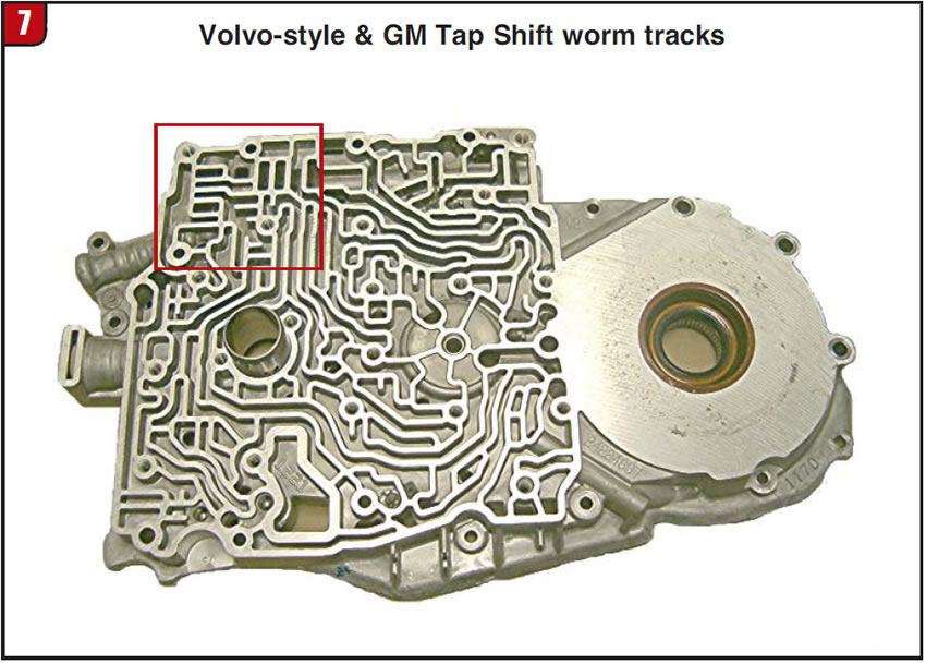
- At the top-left side of the worm-track area GM uses a low blow-off ball and spring that is positioned vertically; Volvo uses a low regulator valve and spring that is positioned vertically.
One or two blow-off balls
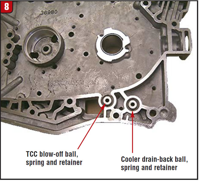
The blow-off ball with the heavier spring is for TCC pressure, and the blow-off ball with the weak spring is for the cooler drain-back. All 4T65-E transmissions have a cooler drain-back ball and spring. Some have it in the channel plate and some have it in the return cooler-line fitting. The transmission must have one or the other, but not both. See Figure 8 on page 36 for the location of the TCC blow-off and drain-back checkballs.
Early or late channel plate
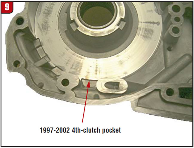
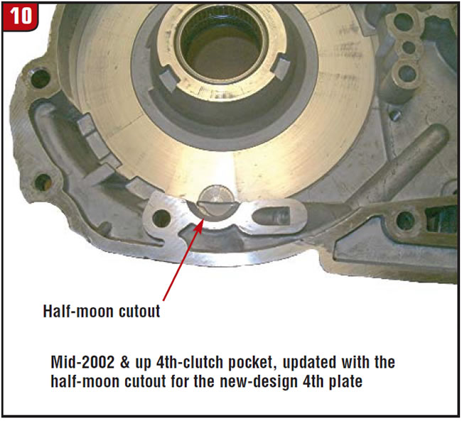
The channel plate can be identified as early or late by the casting number or the fourth-clutch area of the channel plate. The late channel plates have a half-moon cut-out at the 6 o’clock position in the fourth-clutch area (figures 9 and 10).
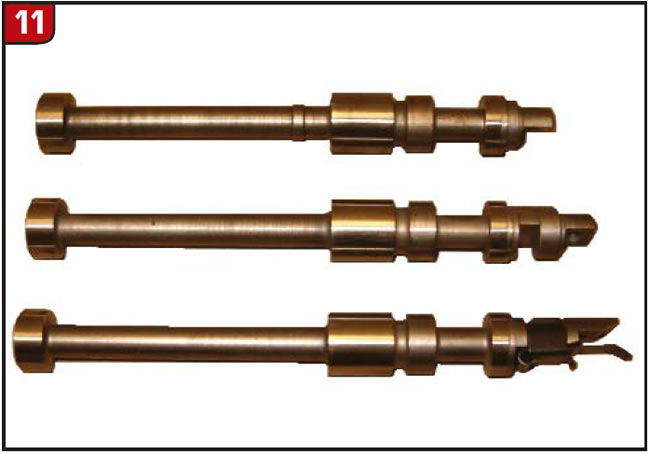
Two other parts that should be mentioned in talking about the 4T65-E channel plate are the manual valves and the turbine-speed sensors.
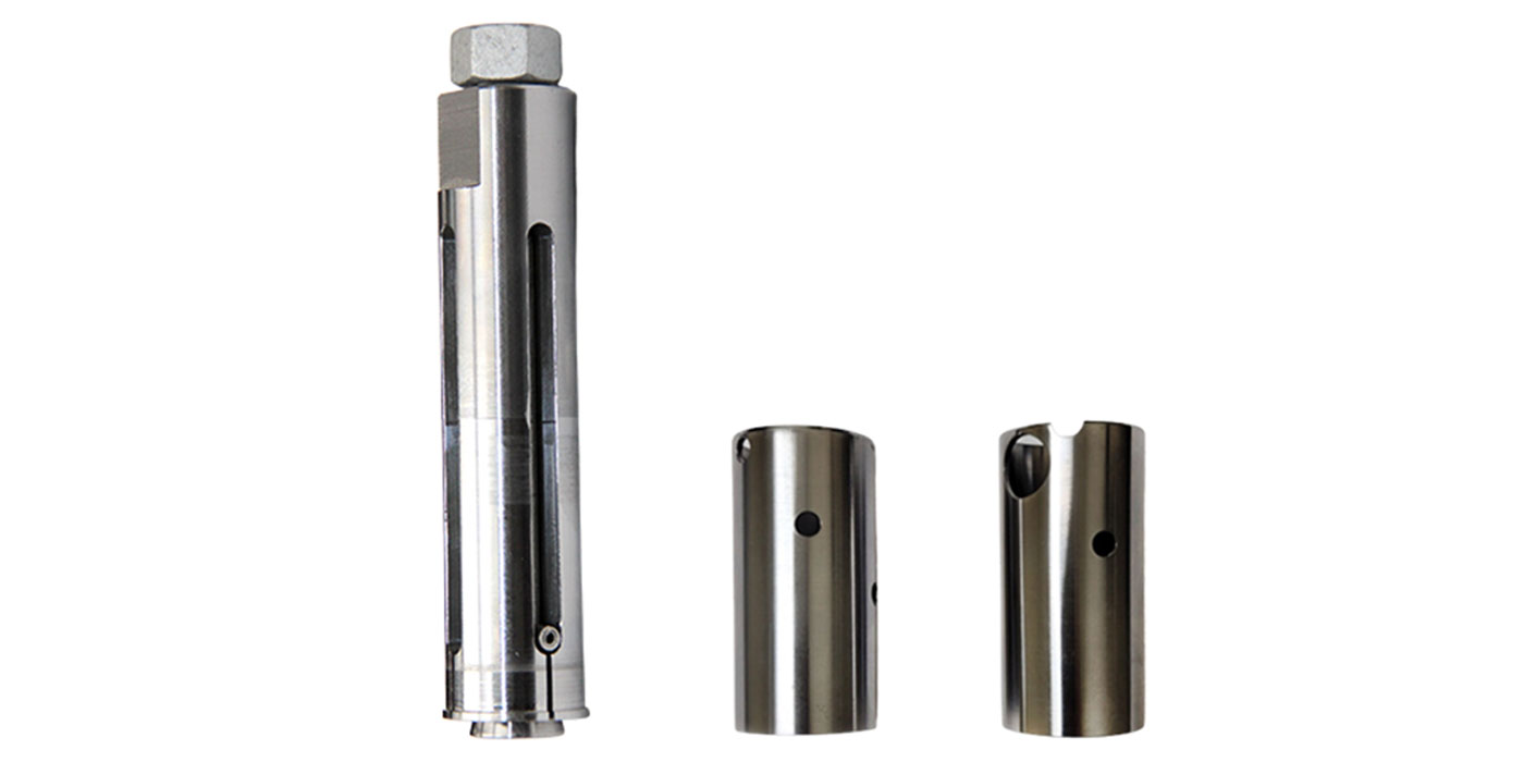
Manual valves
There are three manual valves that I have seen, and all three have the same distance between the two spools that control the oil flow. The differences are in the overall length and the way that the valve connects to the internal linkage. When you are replacing the channel plate, always use the manual valve that came with the vehicle so that it matches the internal linkage (Figure 11).
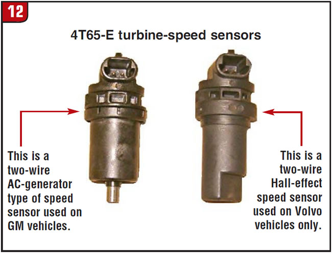
Turbine-speed sensors
GM uses a turbine-speed sensor that is an AC generator, and it has a metal tip protruding from the end. Volvo uses a two-wire Hall-effect turbine-speed sensor, and the end is completely enclosed in plastic. Both speed sensors have the exact same electrical connector (Figure 12), so the harness can be plugged into either sensor and it will look like a good fit. These sensors DO NOT INTERCHANGE! Using the wrong sensor can give you shift problems, codes and TCC problems, plus it is no fun to replace once the transmission is installed.