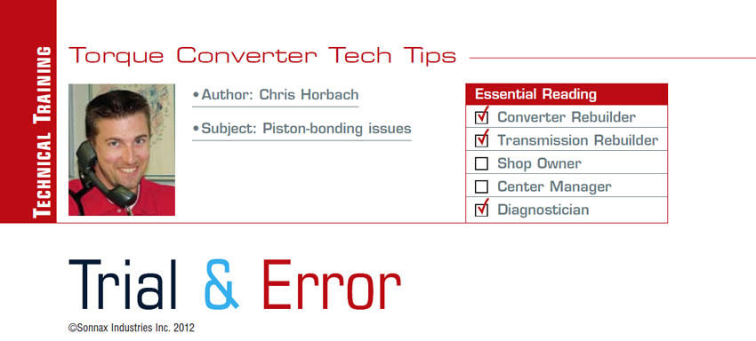
TC Tech Tips
- Subject: Piston-bonding issues
- Essential Reading: Converter Rebuilder, Transmission Rebuilder, Diagnostician
- Author: Chris Horbach
Ever been told that experience is what you get when you don’t get what you were expecting? How true, especially when equipment or simple oversights in preparation have led builders to waste valuable production assembly time chasing a problem. It is through experience, though, that we learn what we can do with confidence. The experience gained becomes gratifying once we have pinpointed the specific cause. As a result, it makes us wiser, reduces the time needed to resolve the issue next time it happens and can help others through technical forums like the one hosted by TCRA and others for transmission rebuilders.
Although the list is exponentially larger than what we have room for here, we’ll explore three very common equipment and piston-assembly issues, methodologies of resolution and whether there are any tools that can help your shop return to production speed sooner:
- Confirming contact pressure
- Temperature correlations
- Root-causing the impact of machining-related issues on bond strength
Contact pressure
Uniform contact pressure on a lockup piston during surface prep and bond and in application during lockup or controlled slip is dependent upon multiple tools and surfaces aligning parallel to one another. Beginning with fixture flatness and parallel relationship of the top and bottom fixtures, the easiest way to confirm both is with a simple solder test conducted at startup with heating elements at room temperature.
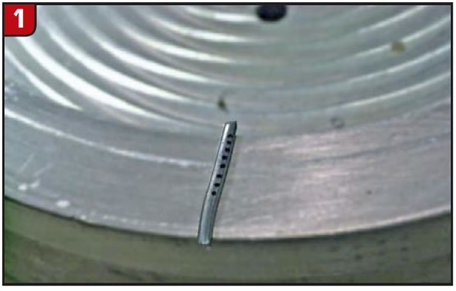
- Step1: Mark solder segments in case the pieces are dropped or shuffled afterward (Figure 1).
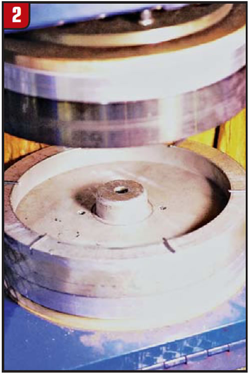
- Step2: Identify locations (12, 2, 4, 6, 8, and 10 o’clock); 6 o’clock in the bond station should be closest to you with the door open; 12 o’clock, of course, will be farthest from you (Figure 2).
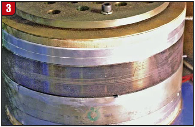
- Step3: Clamp the fixtures under pressure for 30 seconds (Figure 3).
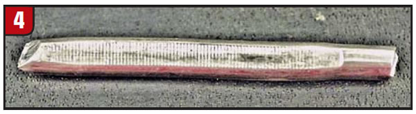
- Step4: Open fixtures, measure and record compressed thickness on both the outer and inner end of the flats on all six pieces, and identify the location from which they came. You might want to place a mark on the fixture itself for reference (Figure 4).
These fixtures yielded the following measurements near the outer and inner edges:
- 2 o’clock: 0.089 inch outer, 0.089 inch inner
- 4 o’clock: 0.088 inch outer, 0.088 inch inner
- 6 o’clock: 0.094 inch outer, 0.092 inch inner
- 8 o’clock: 0.099 inch outer, 0.098 inch inner
- 10 o’clock: 0.097 inch outer, 0.099 inch inner
- 12 o’clock: 0.096 inch outer, 0.095 inch inner
Measurements indicate that the fixtures are parallel within 0.011 inch, and the O.D. to I.D. flatness indicates fixtures are flat from inner to outer edges. From these measurements, we have verified that the current fixture arrangement and orientation will provide less contact pressure between the 8 o’clock and 12 o’clock positions. As a result, the clear decision is to re-machine both surfaces flat and repeat the solder test. Maximum variation should not exceed 0.007 inch around the fixture.
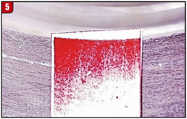
You also can use carbon transfer paper across the face of the fixture (Figure 5) to identify any low/high points as a starting point for locating solder. Again, make sure heating elements are cold and fixtures/components are at room temperature.
Contact paper is more reliable and costs a little more; it also is a good tool to aid in identifying contact loading between the back of the piston being bonded and the fixture, as well as the relationship of the front of the piston to the fixture (with and without material). Contact paper is available in multiple ranges depending on pressures being used. (For reference, I’ve used Pressurex from Sensor Products LLC [pressure range 70 to 350 psi]. Sensor Products Inc., 300 Madison Ave., Madison, NJ 07940, 973-884-1755).
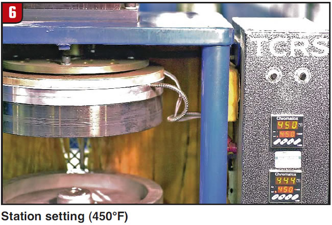
A bond station is only as good as its maintenance history reflects, and it will do what you program it to do with relatively good accuracy; however, it will provide feedback only from what it is capable of controlling. A perfect example is temperature correlation. Let’s say the operator has the machine set at 450°F for both upper and lower fixtures (Figure 6).
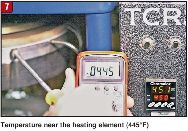
We could say the thermocouple-to-station-setting relationship will yield similar data. Let’s bolt on a steel fixture. Now, measure the temperature of the fixture nearest the edge either supporting the piston or clamping against the friction material on the bond side (Figure 7).
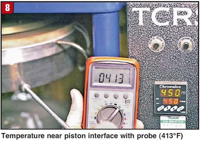
You may be surprised to find out the temperatures at the fixture are an average of 20° to 50°F lower than the bond-station temperature controller (Figure 8). Combine this with a cover having a lot of mass, and actual bond interface temperature is now much lower than you are expecting.

Temperature confirmation
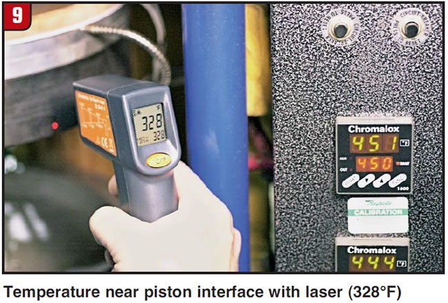
Touch probes are reasonably accurate, and they’ll plug into most DVOMs with temperature option. Lasers (Figure 9) tend to be much less accurate and can be influenced by reflectivity of the fixture.
As long as you know the difference between actual fixture temperatures and setting temperature, you can create an offset by raising control-setting temperature until actual fixture temperature matches desired temperature.
Example: Let’s say the fixture is stabilized at 425°F and the controller setting is 450°F. You will get fixture temperature close to desired temperature by adjusting controller temperature to 475°F. This is not always a proportional relationship, but close. As a result, temperature settings and correlation can become part of the routine maintenance cycle.
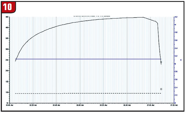
Taking it a step further, data loggers that plug directly into a laptop are available for less than $200. The two-wire J-type thermocouple can be placed directly at the bond line between the adhesive and bond surface to document time/temperature curves. (Note: Either wiping adhesive completely off the test ring with MEK or placing tape over the adhesive in the area the thermocouple will be situated will make it easier to remove once the cycle has finished.) The software that comes with the data logger will plot your T/T curve, and you can export the data to an Excel document for graphing results of multiple settings, confirming repeatability of setups and reviewing temperature impact on piston/cover configurations.
The plot in Figure 10 indicates that this is a typical two-minute bond cycle, steel core/piston temperature reached 350°F in 15 seconds from room temperature, and it reached optimum cure temperature of 400°F in 32 seconds with the remaining time in the cure zone and a peak cycle temperature of 448°F. (Information gained from OE converter products supports the idea that a high-temperature fixture surface will not inhibit material integrity. For example, cottons normally found in what we know as Tan on-off lockup linings won’t burn off until 662°F.)
It goes without saying that the bigger the mass, the longer it will take to heat up and stabilize. Another key consideration is whether the component being bonded to is aluminum or steel. If it is aluminum, you can bet it will pull a lot of heat from the fixtures. In other words, fixture temperatures may be at 475°F before the cycle, but they may drop to 400°F or 425°F during the cycle, and it will then take longer for fixture temperatures to recover before you bond the next part.
Root-causing bond-strength issues
Here are a few questions to ask yourself if you are experiencing irregular-bond issues:
Is it occurring across the entire part? If so, troubleshoot using these guidelines:
- Check washing solution.
- Where do the oil and contamination rinse to, and how is the cleaning solution circulated?
- How often is it changed?
- Check pH level at start and after multiple washes.
Is the issue occurring in one only section of each part?
- Do not move fixture.
- Solder test.
- Confirm flatness of piston.
- Are parts hanging on a rack after being stripped, prepped or after wash?
- Index part in the bond station. If they were hanging on a rack, identify the 6 o’clock position on the rack, place at 6 o’clock in bond station and mark accordingly for reference.
- If bond issue occurs at 6 o’clock, make sure it is repeatable.
- Since it can be either the fixture or a result of the cleaning process, index a minimum of three more parts, but rotate the next trial parts so that 6 o’clock on the hanging piston is at 3 o’clock in the bond station. This will identify whether the issue lies in the part or station tooling.
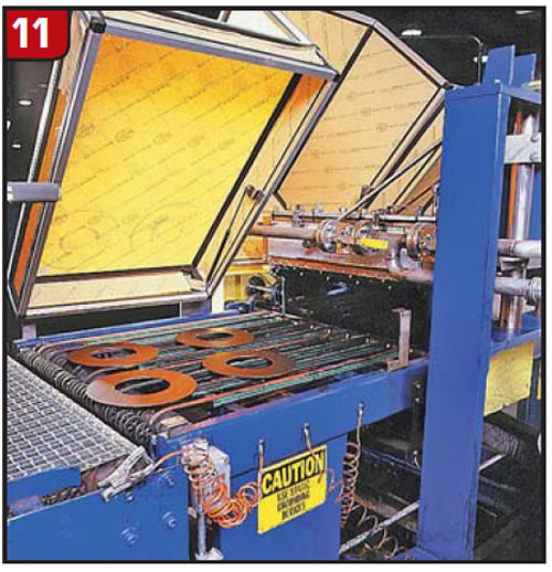
Is the problem occurring on just the O.D. or just the I.D.?
Since friction materials used in our industry are typically coated front to back rather than from O.D. to I.D. or I.D. to O.D., blaming the adhesive for a bad O.D. bond or bad I.D. bond does not address the real problem (Figure 11).
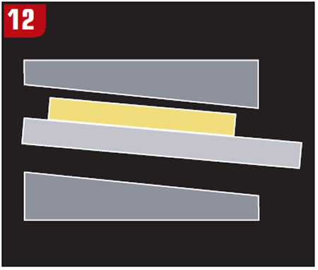
Example 1
Is the piston intentionally tapered inward from O.D. to I.D.? Since some pistons, like the GM 258mm, are formed with a taper having an O.D.-to-I.D. difference of up to 0.012 inch (0.300 mm), it is critical to confirm that the tooling matches the contour of the part (Figure 12).
Example 2
A typical scenario is one in which the bond surface is machined flat and the assumption is that the bottom side is parallel when, in reality, it is a formed part with the same taper on both sides (Figure 13).

If both upper and lower tools are flat, the result will be a good I.D. bond and a poor O.D. bond. The I.D. is resting on the lower fixture, and as the top fixture presses down against the material, the I.D. receives full contact, BUT because of a cantilever action/deflection on the O.D., and because the actual piston is thinner here, it is not fully supported and is receiving only temperature and light contact pressure (Figure 14).

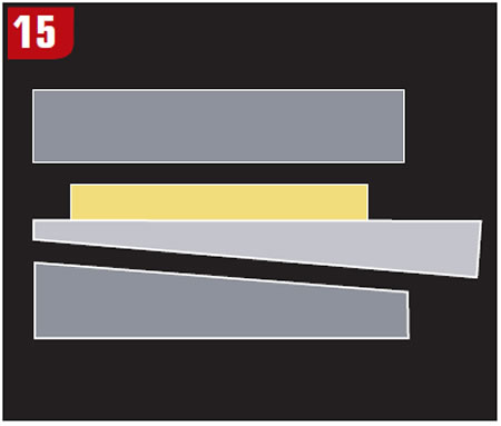
Correction: Make tooling that specifically fits profile of part (Figure 15).
Intermittent-bond issue, where there are alternating good and bad bond sections every X number of degrees?
- It is important to support all 360° of the piston for cutting and prepping, especially with thin materials like the 258mm piston.
- When bond concerns arise at evenly spaced intervals on a part, you will likely find a good bond in the areas that were properly supported on the cutting lathe.
When you are faced with a problem, here are a couple of closing tips to consider:
- Stop and create a design of experiments (DOE) to use as a guideline on methodology of how you will identify the root cause. A DOE is a systematic approach to problem solving that applies principles and techniques at the data-collection stage so as to ensure a definitive conclusion.
- Establish a starting point by identifying variables that affect the outcome.
- Identify which variables are going to be changed in each trial, and record the impact.
- Change only one variable at a time (even though the time it takes might be painful).
- Measure and record all results, even if they impacted the test negatively, so that late in the day you don’t find yourself repeating something you have already tried.
The next time you think you have a problem, ask yourself whom it affects, whether you can fix it and how it compares with the problems of the less fortunate. Turns out, our converter-assembly problems are just inconveniences that lead us to gain experience when we don’t get what we were expecting.
Chris Horbach is a Raybestos product-development engineer and technical adviser who writes on issues of interest to torque-converter rebuilders. Raybestos supports the Torque Converter Rebuilders Association. Learn more about the group at www.tcraonline.com. Sonnax thanks Raybestos for allowing us to share this information with rebuilders.
©Sonnax Industries Inc. 2012