
TASC Force Tips
- Author: Bob Warnke
The most-effective tools are often the ones we make ourselves: the screwdriver with the hook end ground into it for removing snap rings, the broken scribe we welded to the makeshift slide hammer for removing Ford end plugs, or the 2004R valve-body bolts without heads for alignment pins. You know what I’m referring to: those time-saving specialty tools that many wouldn’t recognize.
This article addresses special tools relating to 5R55E and 5R55W/S transmissions. If you have worked on these units, you’ve already discovered how difficult it is to isolate slip codes and TCC problems. These tools are specific to the 5R units, but you can use your design creativity, a cut-off tool and a drill to make test fixtures from other parts as well.
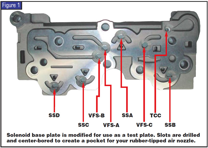
The 5R55 W/S has a solenoid assembly with an aluminum base plate that can be removed. This base plate can be made into a test plate very easily (see Figure 1). The feed circuits identified in Figure 1 have irregular slots, but if you pre-drill with a 3⁄16-inch bit and countersink or use a #5 centering drill, they conform to your rubber-tipped air nozzle perfectly. As with any tool, the more you use it, the more consistent your results. In this instance, it not only saves time but also identifies how functional the valve body is before you remove it!
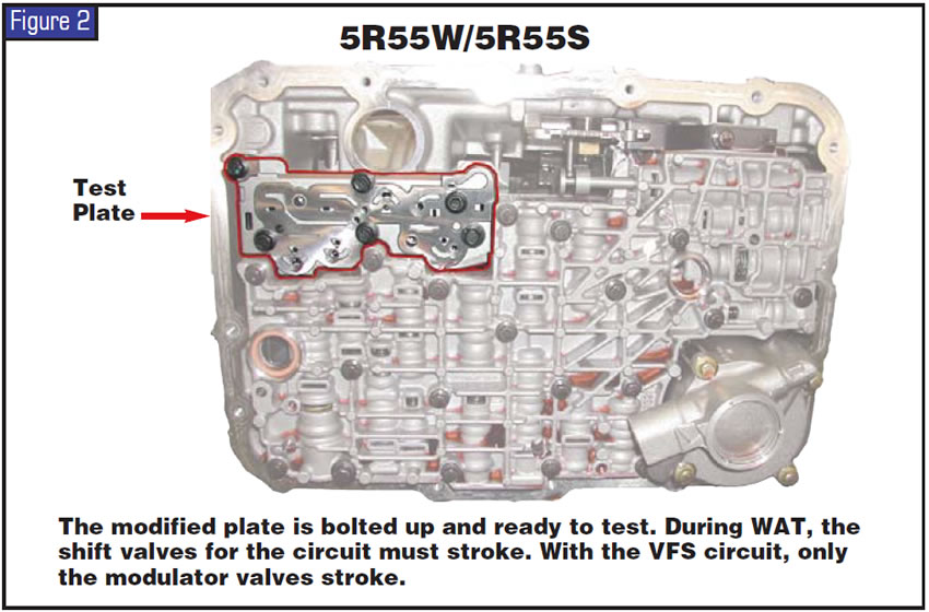
The 5R55W/S, pictured in Figure 2, has problems with slip codes, TCC shudder and delayed engagement. The common practice is to remove the valve body, disassemble the valves and look at the bores. When we do this, we remove the evidence from the case. Warped valve bodies, stuck valves, blown gaskets, worn bores and loose bolts could be overlooked unless you test the circuits before removing the valve body. On these units, the solenoid-circuit test tool can be used while the transmission is still in the vehicle. Within minutes you have the information you need to make a decision on whether the unit has to be pulled or whether you ought to include a valve body in your rebuild estimate.
The 5R55W/S uses a shift solenoid to stroke the shift valve and then uses variable-force solenoids (VFS) to control clutch feed rate and line rise. Shift-solenoid oil is dead-ended when you use the test plate. To test, use ATF and regulated air of about 40 to 60 psi (referred to as a wet air test, or WAT).
5R55W/S shift-solenoid circuits, normal function:
- SSA: Intermediate select valve strokes; direct-clutch control valve strokes.
- SSB: Intermediate control valve strokes.
- SSC: OD servo control strokes.
- SSD: Coast-clutch control strokes: reverse servo control strokes.
- When circuit function is correct, only these stroke and must return smoothly.
5R55 W/S VFS solenoid circuits, normal function:
- VFSA-1: VFS 1 modulator valve and boost valve stroke.
- VFSB-2: Reverse-engagement control, boost valve, VFS 2 modulator valve and forward-engagement control valves stroke.
- VFSC-3: Reverse modulator valve strokes. There must be fluid in this circuit to seat the -A- bathtub checkball.
- TCC: Converter-pressure modulator and converter-control valve stroke.
- When circuit function is correct, you can slowly throttle up and down your air pressure and the valves follow. Oil loss at any location is a loss of the VFS oil force. The amount of oil loss depends on how much air pressure is used, the ATF in the circuit and severity of bore wear. If you practice with known good and high-mileage units, you’ll be able to recognize the problem areas.
Valve-body concerns in the 5R55E’s and 4R44E’s are very difficult to identify once the valve body is removed from the unit. Poor line rise is the most-common concern, which results in delayed forward or delayed/no reverse, slip 1-2, no 2nd or no 2-3. Another concern occurs after forced downshifts. Then, line pressure and EPC may remain high and cause harsh engagements or shifting.
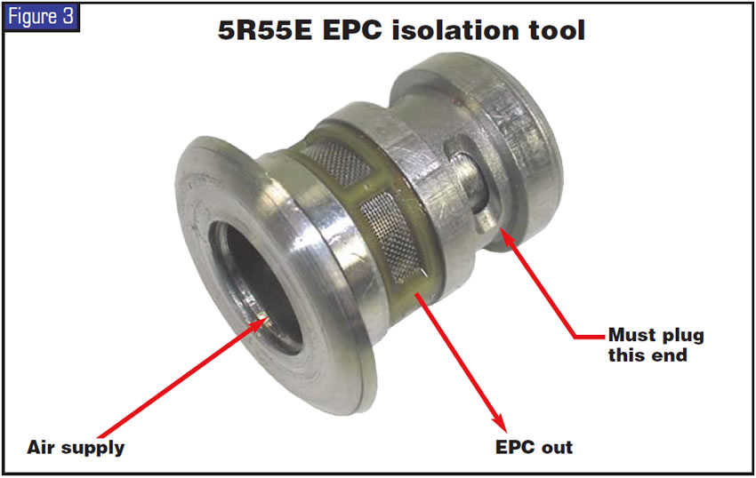
Figure 3 illustrates how to make a tool from a 5R55E EPC solenoid. You can do this same test using a 4L60-E or 4L80-E force motor to isolate GM torque-signal circuits.
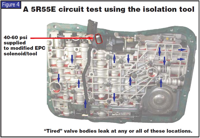
On the 5R55E shown in Figure 4, the regulated air pressure is fed into the isolation tool after removal of the EPC force motor. I suggest you gain experience first on a valve body that works, then on a problematic one. Any oil loss (indicated in Figure 4) is loss of EPC booster oil.
As with any tool, the more you use it, the more useful it becomes. You’ll wonder how many problems you overlooked before you made these. They will undoubtedly be placed in your special-tools drawer.

Bob Warnke is Sonnax technical director and a member of the TASC Force (Technical Automotive Specialties Committee), a group of recognized industry technical specialists, transmission rebuilders and Sonnax Industries Inc. technicians.


