
Technically Speaking
Author: Mike Riley, Technical Editor
Subject Matter: CVTs
Unit: Jatco JF015E
Vehicle Application: Nissan
Issue: Design & operation
The CVT (continuously variable transmission) concept has been around forever, but CVTs have been on the road now for decades, in one form or another. Although there are several different models of CVT, they all have one thing in common: basic operation.
Over the years there have been variations in CVTs from vehicle model to model, starting with the original DAF European CVTs, up to the first Jatco CVT, Saturn VT20E, ZF VT1, Ford CFT30 and then on to later-model Jatcos. There are CVTs that use a torque converter and some that don’t. A CVT may have a push belt, while others use a drive chain. Electrical components also vary widely among models. In addition, certain models use a direct-drive pump while others use a chain-driven remote pump. The CFT30 uses a pump with oscillating pistons. A CVT will also have a planetary gear set, primarily for reverse.
Basic operation, however, consists of the drive chain or push belt being clamped between two pulleys (variators) under high pressure. Ratio (gear) change is provided by the drive- and driven-pulley sheaves (sides) moving sideways toward or away from the center, which forces the chain or belt to walk up or down the pulleys, thus changing the ratio from low to high and back.
The whole purpose of this approach is to keep the engine at optimum speed for performance and fuel economy. As a step-type transmission shifts up through the gears, engine speed climbs between shifts but then drops back, awaiting the next gear. That is why a CVT has better fuel economy, or so the story goes.

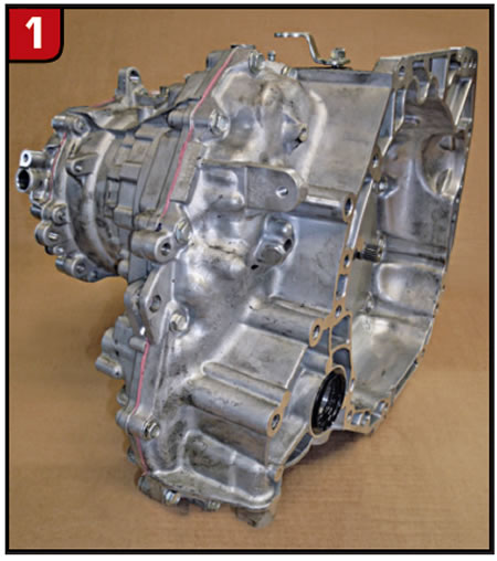
So what is unique about the new Jatco JF015E (CVT7)? The JF015E (Figure 1) actually has a gearbox to provide, in effect, a high/low (stepped) gear, in conjunction with the drive/driven pulleys and push belt. At this point, the question could be asked, “Isn’t Jatco going backward?” The new CVT will literally shift like a regular step-type transmission, as opposed to phantom shifts that certain CVT models have, due to computer strategy. The programmed upshifts give the driver the illusion of a shift.
Is it a CVT or a step-type trans?
The JF015E is a light-duty transmission used primarily by Nissan for small cars. As time goes on, larger models could be developed. The unit uses a relatively flat torque converter. Compared with other CVTs, working on the JF015E isn’t too bad, fortunately.
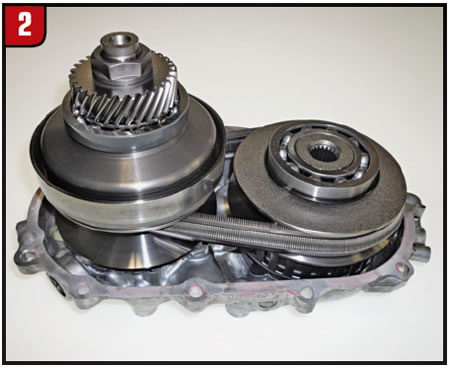
On most models of CVTs, getting to the pulleys and belt requires splitting the bellhousing and case. Gaining access to the JF015E pulleys and belt (Figure 2) merely requires removal of the end cover. In addition, the two pulleys pop out of the cover fairly easily, no clamps needed. When removing the belt, note the position. It should have a directional arrow on it for reassembly.
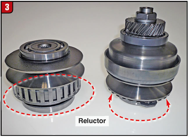
Use caution when removing the pulleys from the end cover to avoid damaging the tone rings (reluctors) (Figure 3). The driven pulley on the left uses a tone ring on the outside diameter (O.D.) of the pulley, whereas the drive pulley on the right has the tone ring at the end.
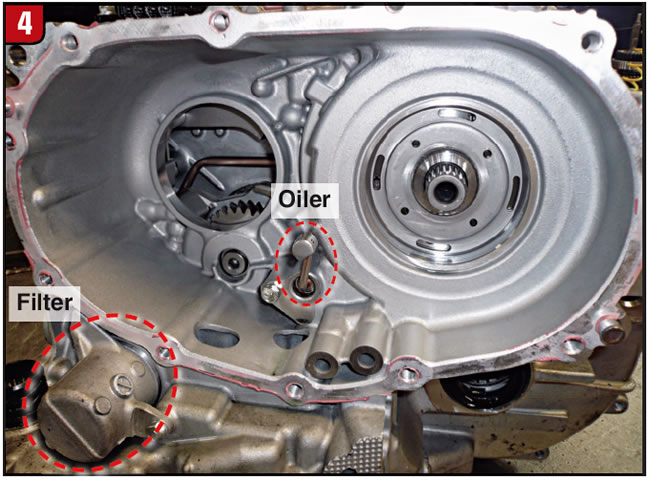
With the end covers and pulleys out of the way, the back cavity of the case is exposed (Figure 4). The input gear appears in the opening on the left. The shaft on the right is the sun gear. An important item in between is the chain oiler. Make sure that it’s not restricted. The cooler filter is at the lower left of the case.
Once the bellhousing and case are split, most of the remaining components are visible (Figure 5). The bellhousing in the foreground contains the differential and pinion gear, whereas the case section has the chain-driven pump and auxiliary-gear-set cover. The cover is held in place by inverted Torx-head bolts.

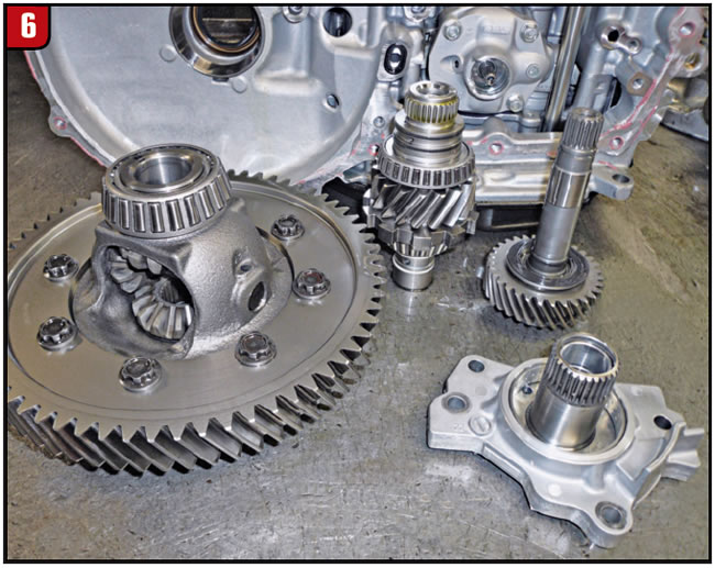
The main drive gears are the input gear with shaft, drive pinion with park gear and differential (Figure 6). The splines at the end of the pinion gear spline to the planet carrier. The stator support contains the converter bushing.
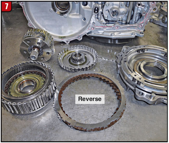
To gain access to the auxiliary-gear section, the cover, which contains the reverse-clutch piston, must be removed (Figure 7). With the cover out of the way, the reverse clutches, direct-clutch drum and planetary set can be removed.
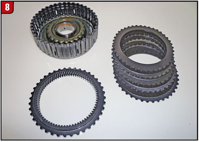
A CVT has two clutch packs, one for forward and one for reverse. The JF015E arrangement is somewhat different. The clutch drum contains the forward clutches as well as the planetary ring gear (Figure 8). When the forward clutch applies, the unit is in direct drive. The outside splines of the drum mesh with the reverse frictions to hold the ring gear stationary.
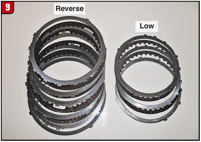
There are two stationary brakes in the JF015E (Figure 9). The large set on the left is the reverse brake, comparable to that of other CVTs. The stationary brake on the right is the low brake. When the low brake applies, the gear set is in reduction. The low-clutch piston is in the case.
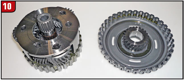
The key item that differentiates a JF015E from the pack is the planetary gear set (Figure 10). Other CVT models use a simple gear set, whereas the JF015E has a compound planet carrier. The small sun gear and shaft splines to the driven pulley and cannot be removed from the planet. The large sun gear and shell is held stationary by the low brake. The planet carrier has splines that mesh with the direct clutch on the O.D. and also has splines that mesh with the pinion gear at the inside diameter.
The main filter is accessible by dropping the bottom pan. The pan uses a gasket and also has a stand pipe for checking fluid (Figure 11). The neck of the filter is long because it extends up through the valve body to the pump.
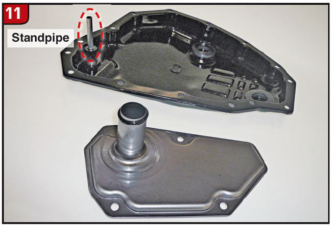
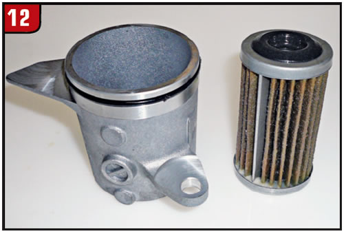
Figure 12 shows the cooler filter and cover that bolt to the case. The filter is a cartridge type.
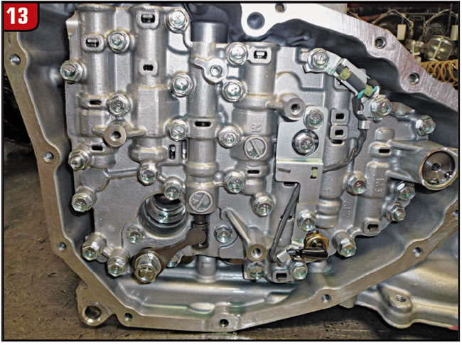
With the pan and filter removed, the valve body is accessible (Figure 13). The manual-shaft lever and nut must be removed first. The electrical connector extends through the case and is removed with the valve body. The bolts that hold the valve body to the case are much longer than the valve-body section bolts, so they cannot be interchanged.
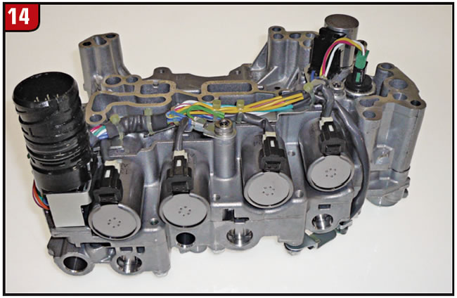
The valve body has the normal amount of stuff. There are five solenoids, a couple of pressure switches, electrical connector etc. (Figure 14). It remains to be seen which parts will become available for sale.
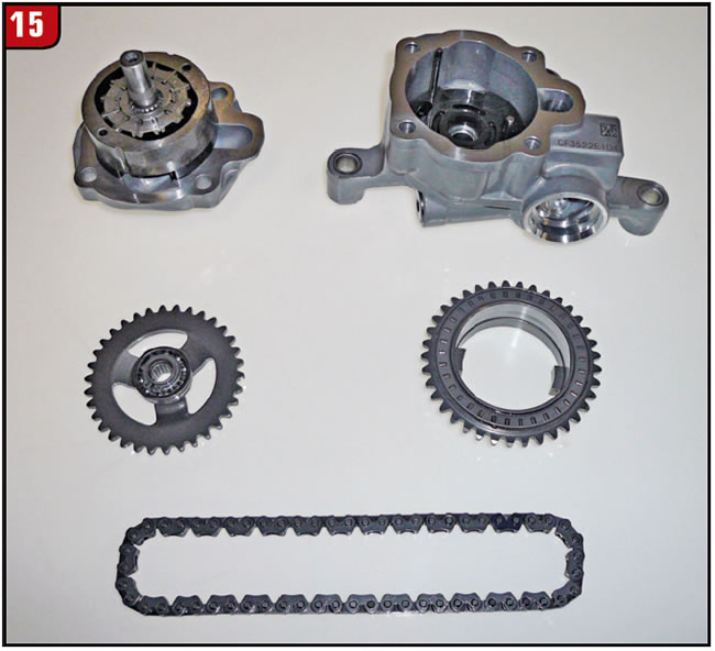
The pump is a remote-design vane type that is driven by sprockets and a chain, as in a 6T70 (Figure 15). The sprockets cannot be flipped; however, the chain can be, so mark it for reassembly. The manual-lever shaft must be removed to get the pump out, but the pump can also be split and removed from the case if necessary.
Time will tell whether any more “step-type” CVTs are released. By using this design, a more-compact CVT is now available for use, but it is a trade-off.


