Technically Speaking
- Subject: Rebuilding continuously variable transmissions
- Unit: Ford CFT30
- Vehicle Applications: Ford Five Hundred, Freestyle & Taurus, 2005-07
- Essential Reading: Rebuilder, Diagnostician
- Author: Mike Riley, Transmission Digest Technical Editor
CVTs are not all created equal
Today’s CVTs are a fact of life because of the number of them on the street. In addition, the flavors (variety) of CVTs have also increased.
One of the more popular CVTs being rebuilt today is in a now-defunct vehicle, Saturn, whereas other CVTs are used by Nissan in vehicles like the Murano. The Nissan CVTs are produced by Jatco, which is the dominant CVT manufacturer in the marketplace today. Jatco has recently released a variation of a CVT that actually has an auxiliary gearbox, making it a partial step-type trans. It almost seems like a “step” backward from a pure CVT.
The CFT30 was produced for Ford by the German company ZF. It was used in the Ford Five Hundred, Freestyle and Taurus, 2005-2007. ZF has since exited the CVT market in favor of eight-speed and even nine-speed transmissions.
Although there are several models of CVTs to contend with, they all basically function the same. One difficulty in dealing with a CVT is diagnosis. Since a CVT operates differently from a step-type transmission, the normal diagnostic approach will need to be altered just a bit to determine what and where the problem is. Fortunately, there is technical information available today; however, more is needed.
Once the problem is determined to be internal and the unit must come out to be repaired, it becomes a matter of just dealing with nuts and bolts – kind of!
As with step-type transmissions, there are differences among CVT layouts. The Saturn VT25E and the Jatco RE0F10A both use remote pumps, which are offset from the engine centerline, whereas the Jatco RE0F09A has a center-mounted pump. The remote pumps are driven by a small chain, but the design will still be able to generate the 700 to 800 psi of pressure needed for CVT operation. All three models use a push belt that consists of hundreds of small elements held together by steel bands.
The CFT30 uses another unique pump design that has eight small pistons and an eccentric cam. The CFT30 also uses a drive chain instead of a push belt. The drive chain looks more like a transfer-case chain, but the pins are what actually contact the surface of the variators (pulleys).
Compared with most step-type transmissions, a CVT contains much less “iron” (planets, clutch packs, supports etc.) with one exception: the variators and chain or belt.
Repairing the variators on certain CVTs can be difficult or even next to impossible, depending on design. The surface finish on the face of the pulley is also important. Make sure that it is not damaged from the chain.
CFT30 disassembly
Once the CFT30 bellhousing and case are split apart and all the easy items are out of the way, the pulleys will then need to be removed. With the drive/driven-pulley covers removed, both 12-point nuts that retain the pulleys are visible. A 2-inch 12-point socket will remove them. Both nuts have right-hand threads. The pulley shafts are pressed into the case bearings, and pressing them out will require some force.
With the case gasket surface supported, either press or hammer both pulleys out together, using caution not to damage the threads or sealing-ring groove.

Variator repair
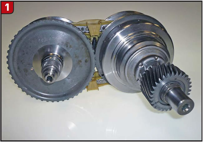
The first thing to do is to separate the two pulleys and chain (Figure 1). The driven-pulley spring force is substantial, but there are a couple of ways to remove the chain.
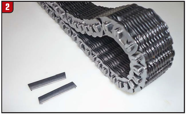
- There are chain pins that either do not have the tiny crimps or had crimps that have worn down (Figure 2). One pin set can be pushed out of the chain to separate it. The problem is the lacing pattern. It’s staggered, and the links must be repositioned correctly when you’re replacing the pins. Note the spacing of each link before pulling the pins. Use caution to avoid breaking the plastic guides.
- Disassemble the drive variator first. It is the easier of the two pulleys. As soon as the retainer housing is removed, the sliding half of the pulley can be separated from the fixed half. Before removing the chain, mark the front side for reassembly, and don’t position it so that any loose pins could fall out.
Tools needed to disassemble the variators:
- Drill press (if possible)
- Acetylene torch
- Center punch/chisel/blunt punch (0.300-inch-diameter tip)
- 3/16- and 5/16-inch drill bits
- 2-inch x 4-inch wood 6 inches long (indent the surface in the center)
- 1/2-inch threaded rod 8 inches long, three nuts
- Two 21/4-inch-O.D. washers, one 1/4-inch-O.D. washer
- #64 bushing driver (1.750-inch O.D.)
- 46mm wrench (or 113/16 will work)
- Gear puller
Drive variator
To disassemble the drive variator, the piston sleeve (retainer) must be removed. It is pressed onto the shaft and can be removed either by using a hammer and chisel, hitting toward the rounded edge at an angle, or by heating the center area with a fire wrench (torch). As soon as the bore of the retainer relaxes from the heat, the Belleville springs should pop it back.
The retainer is thick and can handle the hits or the heat. Just don’t overdo it. The inside surface of the retainer is where the small seal rides. Note the position of the two Belleville springs.
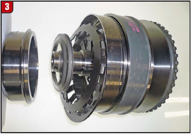
Next, tap off the small seal support and slide off the rear pulley half (Figure 3). Remove the seals.
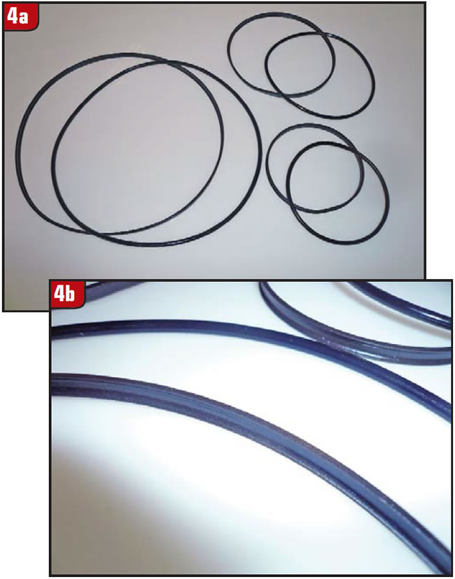
The CFT30 seal design is also unique in that the outer seal is a U-shaped (cupped) graphitic Teflon material and the inner seal is an O-ring. It has compression similar to that of the 4T60-E Vespel/quad-ring design (Figure 4).
Driven variator
To disassemble the driven variator requires a little more effort. Use a gear puller to remove the output gear. Then, using a hammer and chisel, tap off the inner seal sleeve, similar to the drive-variator retainer procedure, except that the driven-seal sleeve is thinner. Stay away from the seal surface by keeping close to the rounded edge of the sleeve.
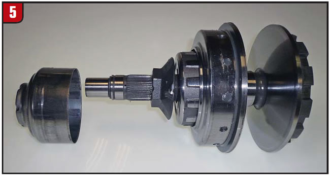
Once the sleeve is removed, the shaft nut is next (Figure 5). Clamp the notched end of the variator in a vise and using a 46mm (113/16-inch) wrench, remove the nut. Removing the nut also may take a couple of whacks with a chisel, because of a high torque load.
With the nut removed, tap the gear end of the variator on a block of wood on the floor, and the sliding half of the pulley should come loose.
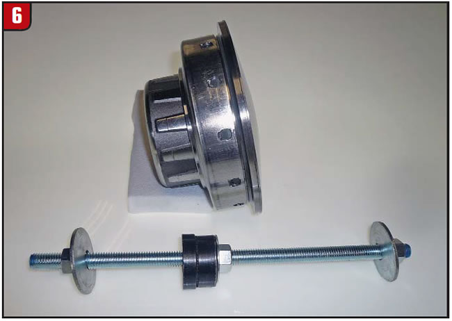
The O-ring shell is crimped to the pulley in 12 places, which must be drilled out. Before drilling out the punch marks, insert the 8-inch threaded rod along with the #64 driver and washers through the pulley to retain the spring and provide a means to press apart the assembly (Figure 6).
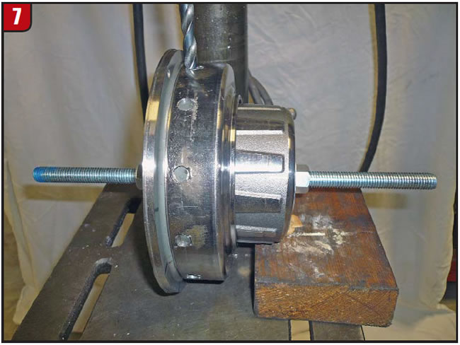
Once the threaded rod is installed, center-punch each of the 12 punch marks and place the assembly onto a drill press, if one is available, to drill out. Set the 2×4 with a concave area cut into it under the pulley hub to keep the pulley level (Figure 7). Drill each punch mark with the 3/16-inch drill bit first.
Note: The shell is soft but the pulley is hard as nails. It can’t be damaged by the drill bit, but the bit may need to be sharpened after drilling a few holes.
Next, drill the holes with the 5/16-inch drill bit. After drilling the holes, grind the tip of the bit down a little so that the cutting edge somewhat resembles an end mill.
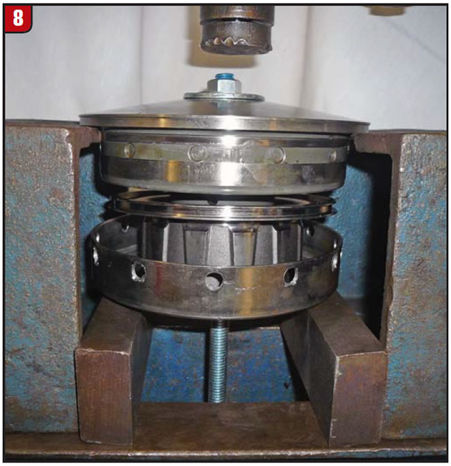
Then, drill the holes to remove the hole radius. Once the holes are drilled, place the pulley edge on blocks in a press and, using the threaded rod and #64 driver, press the hub and sleeve off the pulley. (Even with the holes drilled out, it may require using a press.) Leave sufficient clearance at the top nut to allow the hub to separate from the pulley. Last, unscrew the nuts to relax the spring, which is like an A500 overdrive spring (Figure 8).
Clean and de-burr all components and, if necessary, polish the chain surface of the pulley halves. Replace or reuse the seals (if needed). Note: The aftermarket is developing better, more-user-friendly seals. Until then, use the OE design.
Reassembly
Drive variator
With the components cleaned and inspected and the seals installed, reassemble the drive variator. Make sure the Belleville springs face the right direction. Leave the retainer loose so that the chain can be reinstalled easily. Once the chain and driven pulley are in position, place a sleeve between the retainer and lock nut. Tighten the nut to press the retainer back into position.
Driven variator
With all components prepared and seals installed, mark each of the 12 holes in the pulley for reference so that once the sleeve is in position you’ll know where to re-crimp.
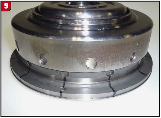
Using the threaded rod, compress the seal hub, spring and pulley half back together. Place the crimp sleeve onto the pulley and tap into position. The original crimp holes of the sleeve should be in the center of the pulley holes (Figure 9). With the sleeve in position, use the blunt center punch to make new crimps. The oil pressure at this area is balance oil and leakage is not a problem.
Reassemble the pulley half onto the shaft and replace the 46mm nut. Use some Loctite on the threads and tighten.
Before installing the thin seal sleeve back onto the hub, grind a small chamfer on the leading edge so that it doesn’t cut the O-ring. Press the output gear back on and install the clip.