Leeward Tech
- Author: Ed Lee, Contributing Editor
- Subject Matter: Toyota’s TCC Shudder Problems
- Issue: Lack of Positive Seal
The Toyota shudder issue
Part 1 of at least two parts
Toyota has been plagued by torque converter clutch (TCC) issues for many years. The shudder issues started with the on-off lock strategy and continue with the present-day advanced strategies. Any Toyota 2002 and newer front wheel drive vehicle can have this issue. There are currently two technical service bulletins (TSB) that address this issue.
- T-TCI-5056 was issued Nov. 24, 2017, and it superseded T-TCI-4148. Interestingly T-TCI-4148 superseded another TSB.
- T-SB-0312-17 was issued Nov. 13, 2017, and it superseded T-SB-0034-14 and it superseded T-SB-0086-12.
The early TSBs recommended replacement of the transmission, torque converter and ECM. If the problem occurred a second time, the recommendation was then to only replace the transmission and torque converter and reprogram the ECM. If the problem occurred a third time, the TSB recommended to only replace the torque converter. Currently some vehicles are on their third torque converter. The current TSBs only recommend to replace the torque converter and reprogrammed the ECM.
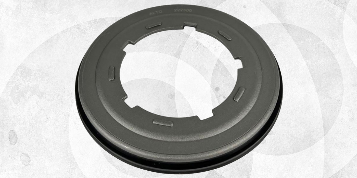
If you look at the TCC apply circuit, it is not difficult to see why Toyota continues to have shudder issues with their converters. There is no positive seal between the input/turbine shaft and the turbine hub. The input/turbine shaft has a smooth area at the end of the splines (Figure 1).
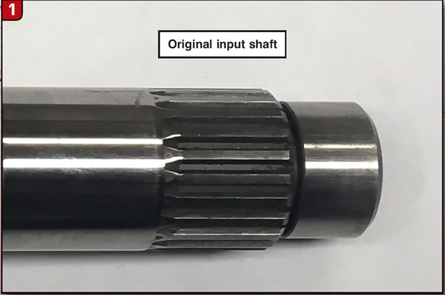
It looks like it was designed to mate to a seal, but the inside diameter (I.D.) of the turbine hub does not have a seal. The I.D. of the turbine hub has the splined area that mates to the input/turbine shaft and also has a smooth bore area (Figure 2).
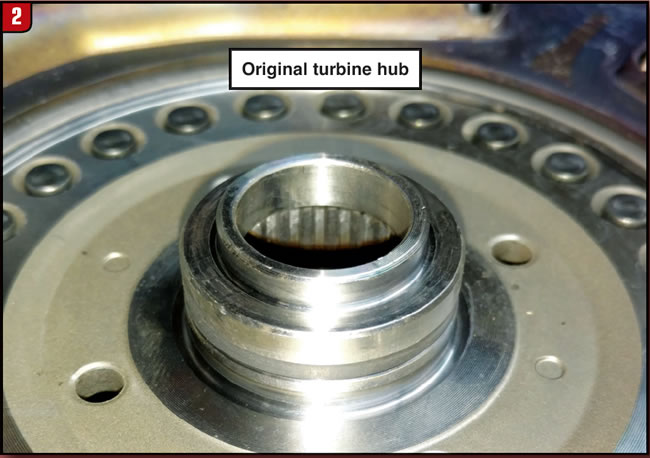
This smooth bore area looks like it was designed to mate to a seal, but there is no seal on the input/turbine shaft. This converter relies on the interference fit between the smooth area of the input/turbine shaft and the smooth area on the I.D. of the turbine hub to seal the TCC apply pressure.

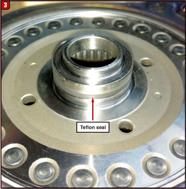
The outside diameter (O.D.) of the turbine hub does have a seal that mates to the I.D. bore of the TCC piston (Figure 3).
If you check a converter that does not have a shudder issue, you will find about 0.0015” clearance between the input/turbine shaft smooth area and the smooth area on the I.D. of the turbine hub. This amount of clearance will give you a leak of a little less than ½ gallon per minute (GPM). If you check a converter that has a shutter issue, it will have about 0.003” clearance between the input/turbine shaft and the I.D. of the turbine hub. This amount of clearance will give you a leak of a little less than 1 GPM. This seems to be the threshold for the shudder issue. The addition of a positive seal in this area fixes the shudder problem.
Fixing the problem
There are a couple of methods of addressing the lack of a positive seal. If you work with transmissions as well as torque converters, you can add an O-ring seal to the input/turbine shaft (Figure 4).
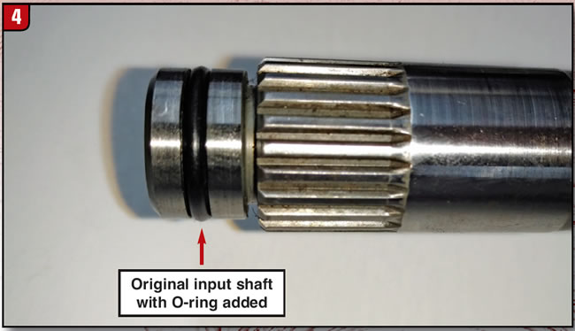
Choose a Viton O-ring that will fit the I.D. bore of the turbine hub. Your gasket and seal company will be glad to help with this. Then machine a groove in the smooth area of the input/turbine shaft with a 1/8 carbide parting tool. Center the groove in the smooth area. Having the O-ring stick out of the shaft about 0.015” on each side will give you a good fit.
If you only work with torque converters you will have to think outside of the box to add a positive seal. When Toyota originally designed this converter, they figuratively painted themselves into a corner. With the exception of a clutch-pack design, there are two options for designing this converter.
The first option is to have the turbine hub contact the cover. With this design you have about zero inches to 0.010” of end play and the clutch release clearance is adjusted separately to about 0.030” to 0.035”.
The second option would be to not have the turbine hub touch the cover. With this design the TCC clutch rests on the cover and your end play is your clutch release clearance (about 0.030” to 0.035”).
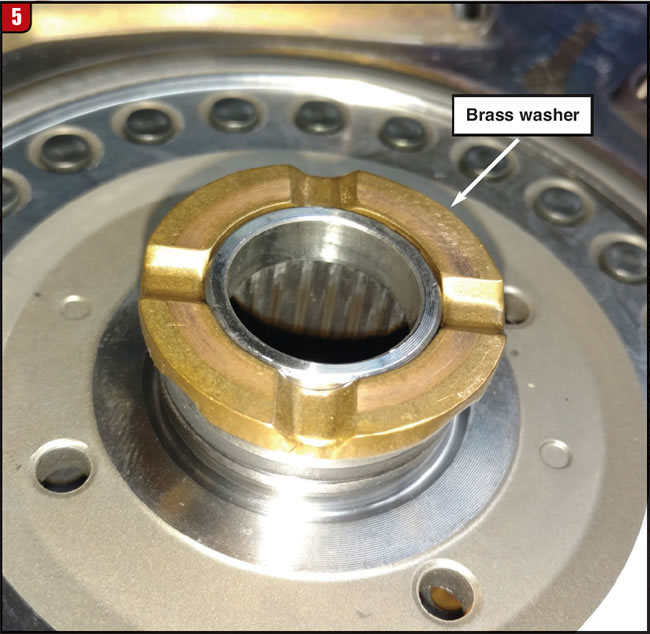
Toyota obviously chose option 1, making it necessary to have a brass washer between the turbine hub and cover. With the brass washer and the step on the turbine hub to center the washer, there was no room for a seal. That is how they painted themselves into a corner (Figure 5).
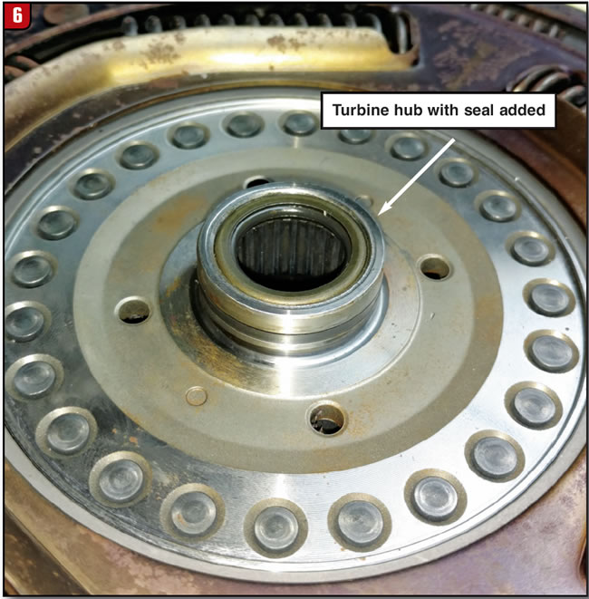
Thinking outside of the box, if your turbine hub does not touch the cover, you do not need the brass washer or the step on the turbine hub that centers the washer. This leaves sufficient room to add a seal. The seal in Figure 6 is from a CD4E converter. It fits the input/turbine shaft well and has a narrow cross section. It is available through two different aftermarket suppliers: Part #FD-O-7V or #FD-25-9.
If you are rebuilding your converter with Option 2, you will need to advise your converter welder to adjust the back off to achieve about 0.030” end play/clutch release clearance post weld.
With a converter that fixes a problem, you can be a real hero with the Toyota people and you may even be able to pick up some Toyota dealer work.