Technically Speaking
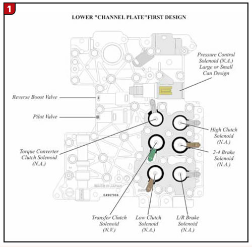
- Author: Wayne Colonna
- Subject Matter: Clutch control solenoids
- Issue: Relocation and accomodation
CHANGE:
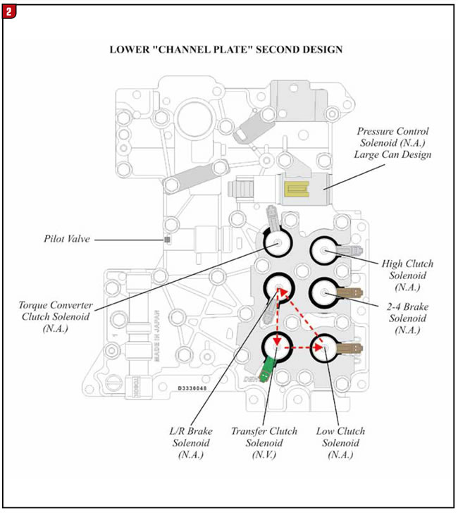
Sometime at the beginning of the 2004 model year, Subaru redesigned the 4AT Phase ll Control system that placed the transfer clutch control solenoid into the valve body. The new design valve body (referred to as Version II) contained 3 clutch control solenoids, 2 brake control solenoids, a TCC and pressure control solenoid (Figure 1).
Through the years both subtle and drastic changes have occurred. The subtle change is noted in figure 1 where the pressure control solenoid went from a small-can design to a large-can design.
The more drastic change can be quickly identified by noticing the elimination of the reverse boost valve (compare figures 1 and 2). Another drastic change that can be quickly identified is solenoid location. The transfer clutch solenoid was moved to the low clutch solenoid position, the low clutch went to the L/R brake solenoid position, which placed the L/R brake solenoid into the transfer clutch solenoid’s original position (compare figures 1 and 2).
This necessitated the need to change both the upper and lower valve body castings and spacer plate.
PARTS AFFECTED:
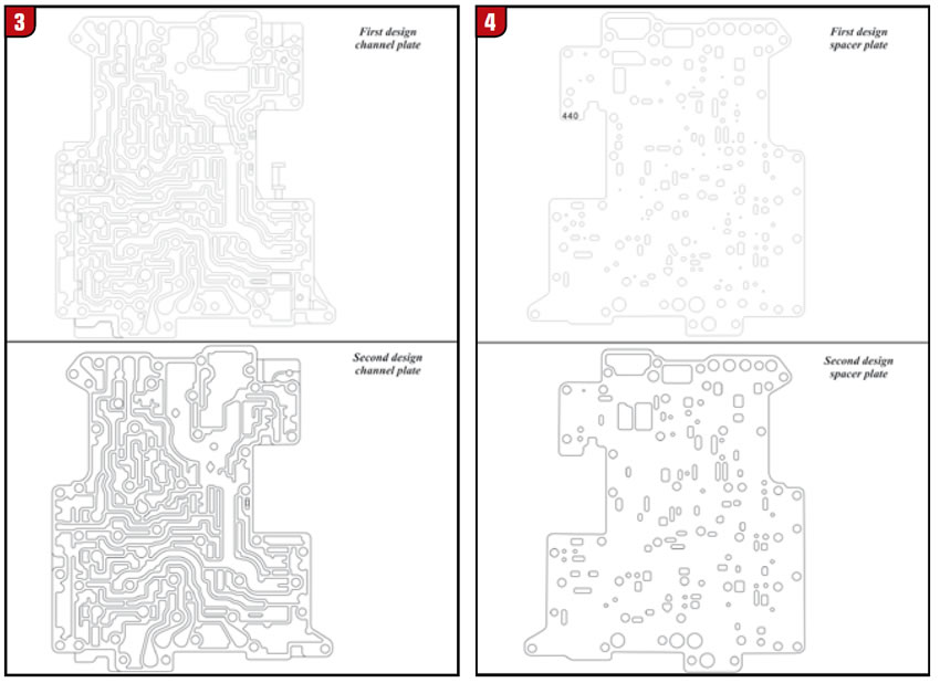
- LOWER “CHANNELPLATE” VALVEBODY – With the reverse boost valve eliminated and three solenoids relocated, it became necessary to change the casting accommodating new hydraulic circuitry (Figure 3).
- SPACER PLATE – Hole changes were made to accommodate new hydraulic circuitry (Figure 4).
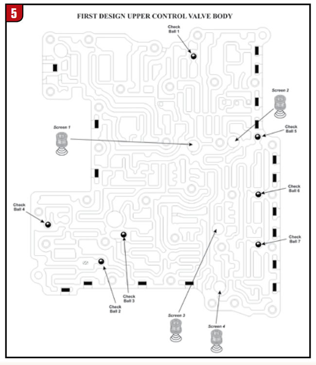
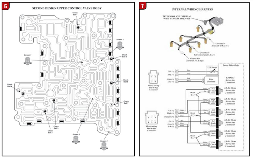
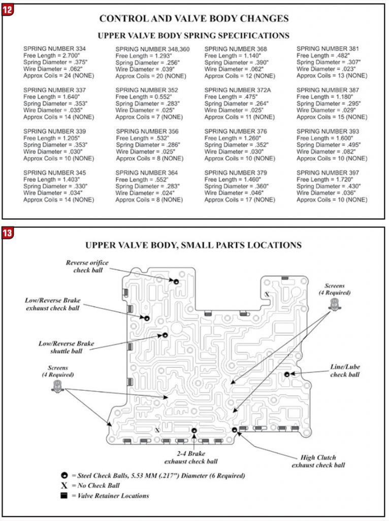
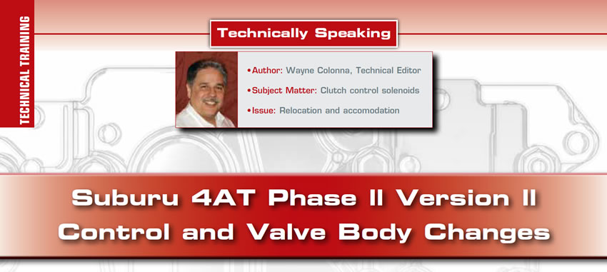
- UPPER”CONTROL” VALVEBODY – With the reverse boost valve eliminated and three solenoids relocated, it became necessary to change the casting accommodating new hydraulic circuitry. This caused one filter to be relocated and one check ball (#7) to be eliminated (figures 5 & 6). The pressure regulator valve and the TCC and lube regulator valve were also redesigned.
- INTERNAL WIRING HARNESS – With three solenoids being relocated, the internal wiring harness has been rewired to accommodate new solenoid positioning. Terminal identification remains the same (Figure 7).
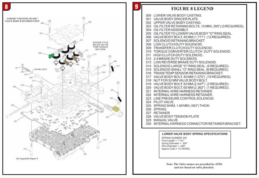
- VALVE BODY ASSEMBLY – Refer to figures 8 and 9 for lower channel plate exploded view and legend. Refer to figures 10 and 11 for upper valve body exploded view and legend. Refer to figure 12 for upper valve body spring specifications. Refer to figure 13 for upper valve body small parts and check ball function and locations. Refer to figure 14 for the hydraulics of this later design valve body. Note: The Valve names are provided by ATSG and are based on valve function.
INTERCHANGEABILITY:
None of the parts listed above are interchangeable with previous design.