Technically Speaking
- Subject: Operation of pressure-control and multiplexer solenoids
- Unit: VW DSG 02E
- Vehicle Applications: 2004-up New Beetle, New Jetta, Golf GTI
- Essential Reading: Rebuilder, Diagnostician
- Author: Wayne Colonna, ATSG, Transmission Digest Technical Editor
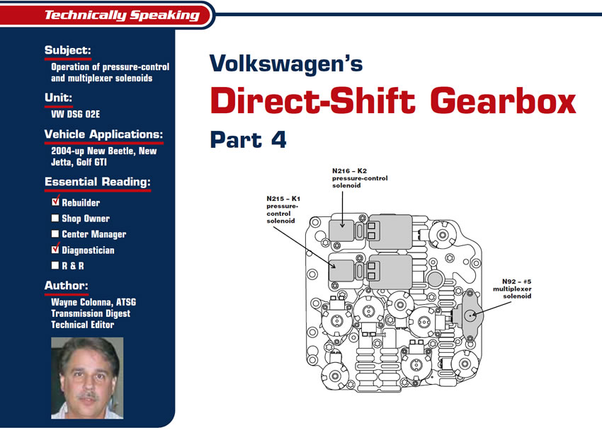
Picking up where we left off last month, the remaining three solenoids to cover are two pressure-control solenoids – N215, which operates the K1 clutch, and N216, which operates the K2 clutch – and the N92 multiplexer solenoid (see Figure 1).
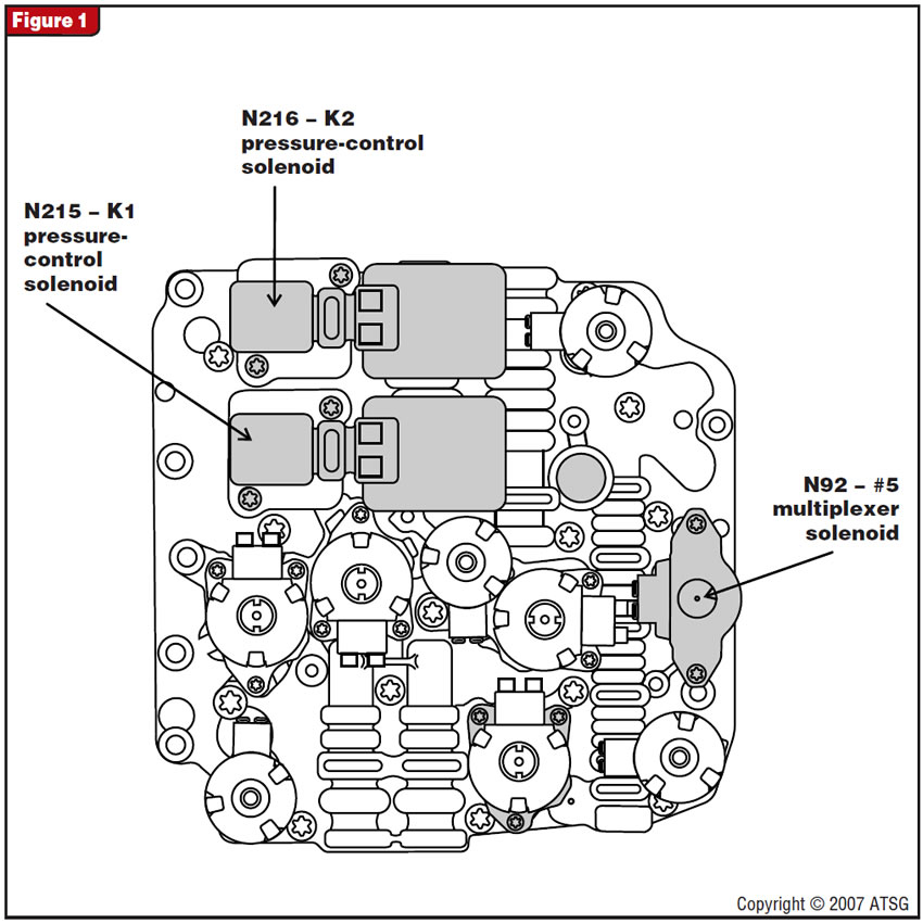
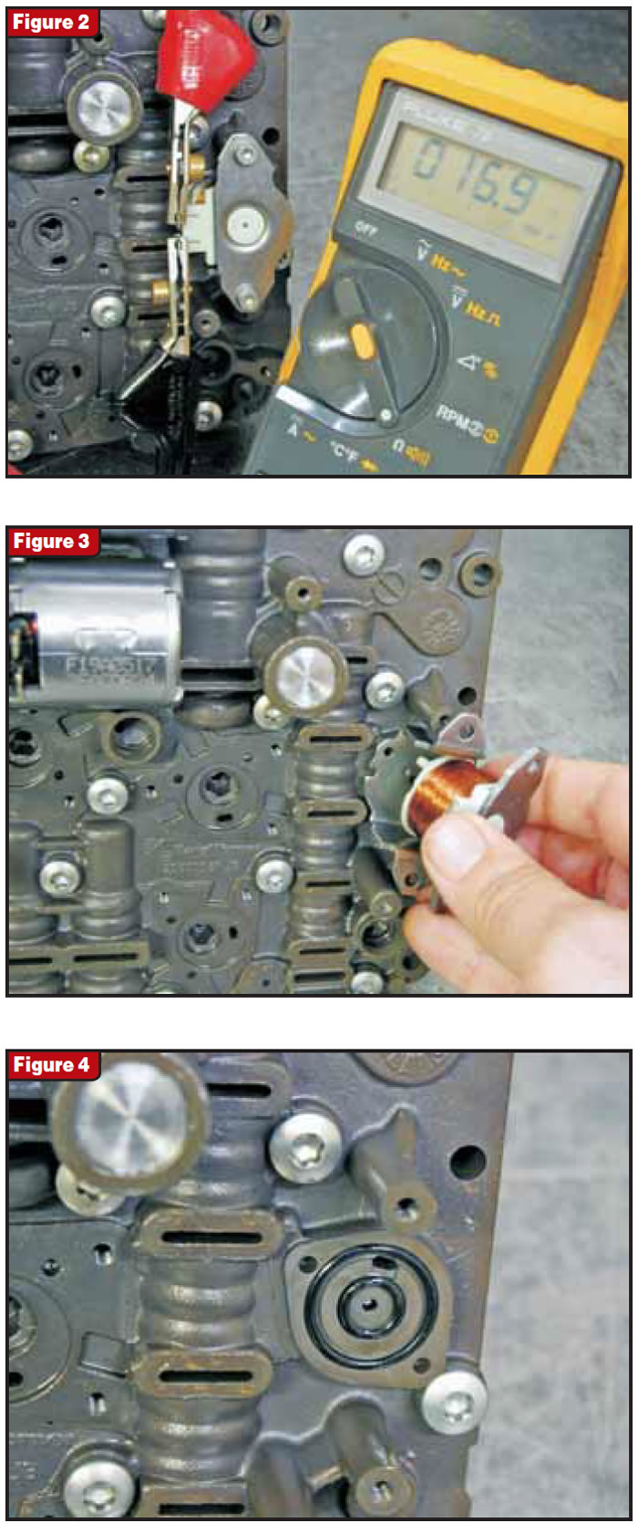
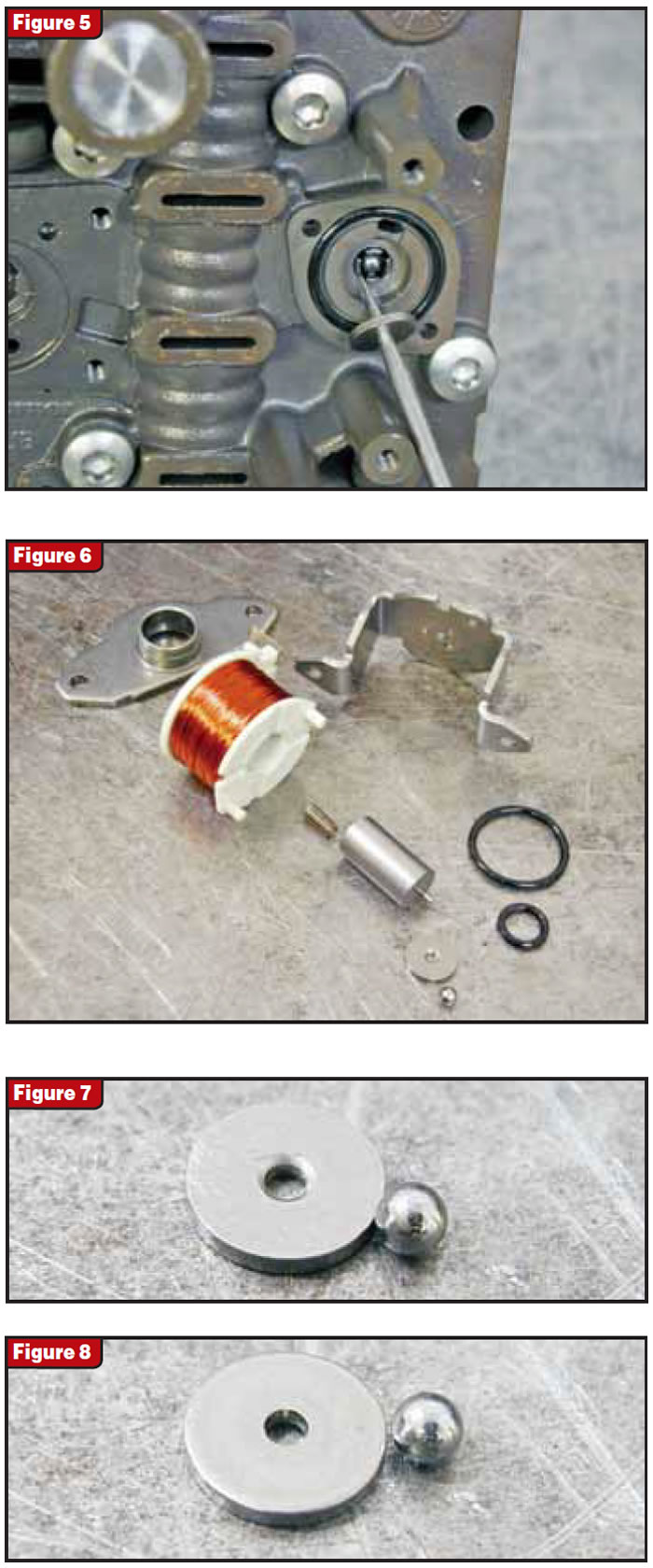
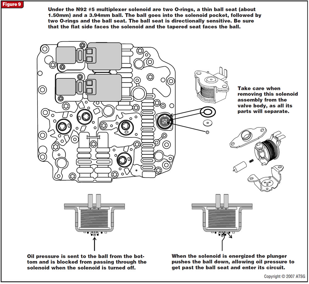
The multiplexer solenoid measures about 15 to 20 ohms, as shown in Figure 2. Be careful not to lose parts when removing this solenoid, as there are two O-rings, a directional ball seat and ball under the solenoid (see figures 3 through 5). Additionally, the attaching bolts hold together the solenoid assembly, which will fall apart in pieces as you can see in Figure 6. Figures 7 and 8 are close-up views showing the ball seat and non-ball seat side of the disc which must be installed correctly. Figure 9 shows details of the solenoid operation.
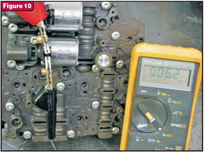
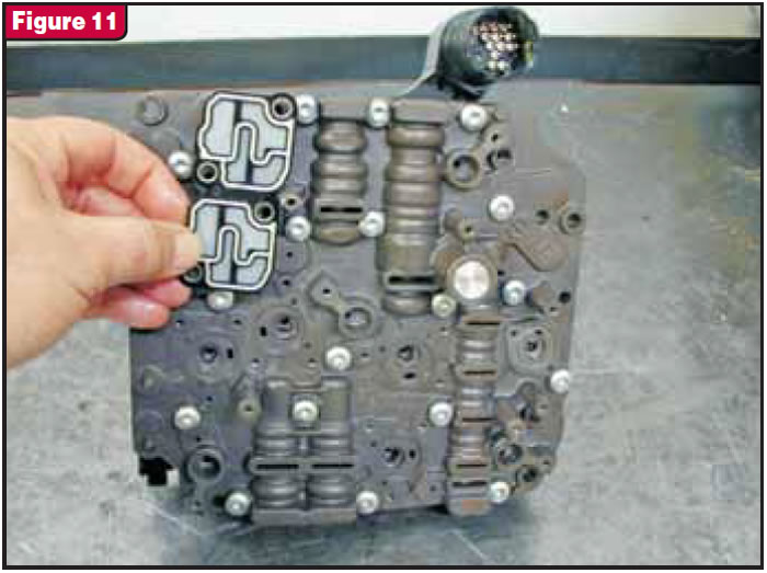
The N215 and N216 solenoids measure 4.5 to 6.5 ohms as seen in Figure 10. When these two solenoids are removed, there is a one-piece silicone-beaded screen gasket similar in construction to Ford’s 5R110W valve-body gasket (see Figure 11). We have seen the negative effects mineral spirits have on the white silicone bead, and so my suspicion is that mineral spirits would damage the silicone bead on this screen gasket as well.
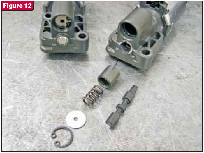
Each of these two solenoids consists of a free-floating valve and a spring-loaded accumulator (see Figure 12). The valve is held in place by a pressed-in bore plug that is not removable – unless, of course, you drill into it and pull it out as I did. It is much easier to just shake the assembly to verify that the valve is not stuck.
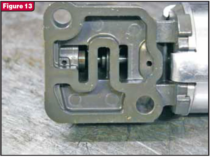
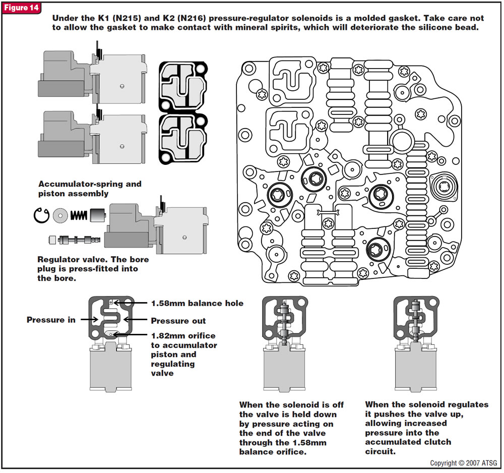
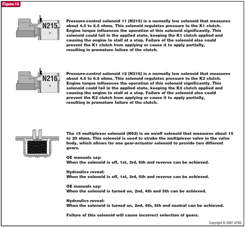
Looking into the hydraulic side of the solenoid there are two orifices, one feeding the back end of the valve and the other feeding the accumulator piston and clutch circuit (see figures 13 and 14). Figure 14 provides the operation of these clutch-control solenoids as well as orifice identification and dimensions. Figure 15 provides further details on the K1, K2 and multiplexer solenoids.
Next month’s final installment on the DSG transmission will provide identification of the valve-body small parts and circuits, case-passage identification, shift-rail operation and TCM information.


