
Technically Speaking
- Subject: Diagnosing speed-sensor problems
- Unit: AF23/33-5 (AW55-50SN)
- Essential Reading: Rebuilder, Diagnostician
- Author: Wayne Colonna, ATSG, Transmission Digest Technical Editor
The input-shaft and output-shaft speed sensors used in the AF23/33-5 (AW55-50SN) are two-wire Hall-effect sensors, which means they are supplied with a voltage source on one wire and send a signal back to the computer on the remaining wire.
GM’s technician guide contains a misleading statement that the sensor is supplied with a reference voltage of 0.6 volt. It also stipulates that the size of output voltage does not depend on a rotation number and is fixed at 1.4 volts. Accompanying these statements is a graph showing a square-wave pulse that starts at 0.6 volt and is driven as high as 1.4 volts.
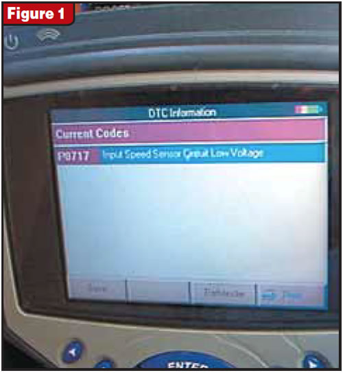
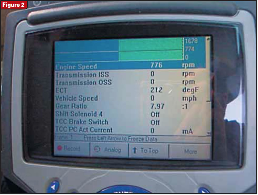
So without a vehicle, this information was difficult to process to the place where you really felt you knew what it was talking about. We could assume what these statements mean on the basis of the graph, but nothing is better than the real deal: a car and a voltmeter. And that is what we have, a 2003 Saturn Vue in failsafe. The scan tool in figures 1 and 2 reveals that we have an input-speed sensor (ISS) that is down.
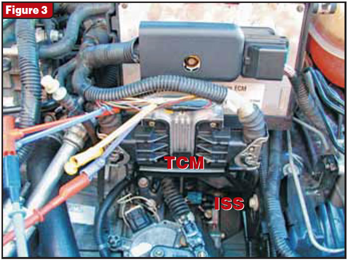
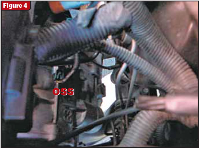
What is really nice about diagnosing this sensor is that the ISS and the TCM are right there in front of the engine compartment, and you can see them as soon as you open the hood (see Figure 3). And since the output-speed sensor (OSS) was also easy to get to (see Figure 4), I was able to attach an eight-channel PC-based diagnostic scope from ATS onto all four wires (see Figure 5).
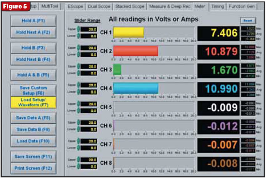
This way I could compare both the voltage-supply and signal wires of the ISS with those of the OSS.
- Channel 1 is reading the ISS signal wire
- Channel 2 is reading the ISS power wire
- Channel 3 is reading the OSS signal wire
- Channel 4 is reading the OSS power wire
With the “key on engine off,” the meters reveal that both the ISS and the OSS are supplied with near-system voltage. Neither sensor is being excited, yet the ISS is showing 7.4 volts and the OSS is showing 1.6 volts. Since the OSS is working and the ISS is not, this could mean only that either the sensor is bad or that the signal wire is shorted to power somewhere between the sensor and the TCM. So the ISS was unplugged and the signal wire was checked for voltage, and there was none. This eliminated the possibility of a short to power, and I concluded that the ISS was defective.
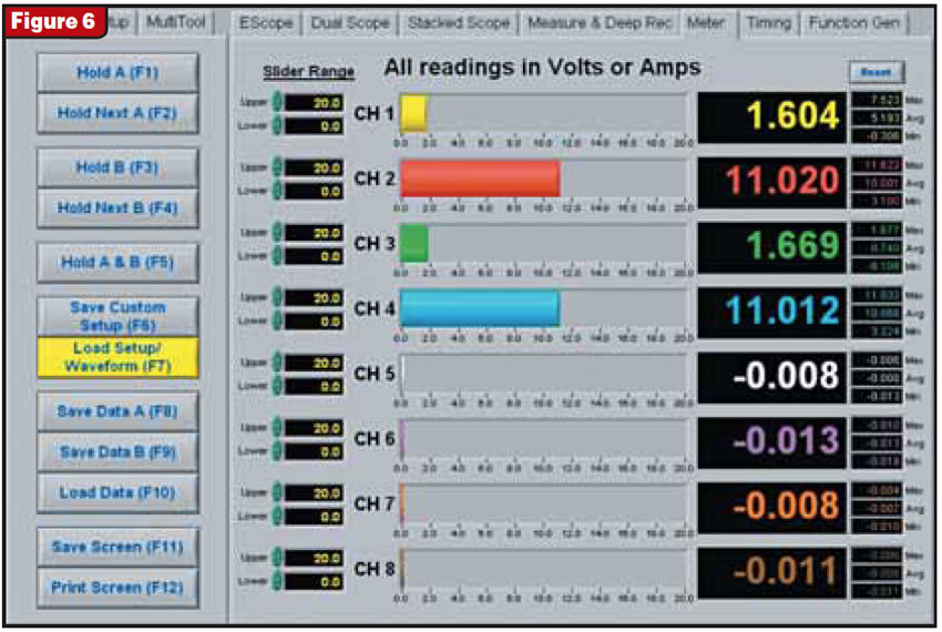
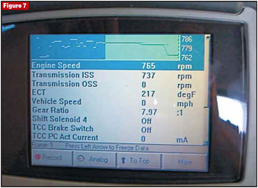
Once the ISS was changed the readings were nearly the same as those of the OSS (see Figure 6). I then started up the vehicle and the scan tool showed that the ISS was finally producing a speed signal (see Figure 7).
With the ATS E-Scope attached, I switched over to the Stacked Scope display and took the vehicle for a little spin. Figure 8 is a screen capture showing the pulse signals of both the ISS and OSS.
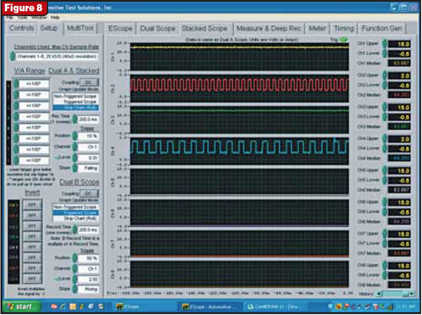
Now, I need to apologize at this point. When I hooked the scope back up to the system, I inadvertently reversed the leads, so the scope will not match what we saw during the meter display in figures 5 and 6. The channels now reflect the following:
- Channel 1 is reading the ISS power wire
- Channel 2 is reading the ISS signal wire
- Channel 3 is reading the OSS power wire
- Channel 4 is reading the OSS signal wire
I then switched over to the Measure and Deep Record display, where these signals can be looked at more closely. Figure 9 shows an overlap of both the power supply and the pulse signal of the ISS and OSS. At the top of the screen you can see that both sensors are supplied with 12.5 to 13.0 volts when the vehicle is running. The pulse signal of both sensors is visible at the bottom of the screen. Zooming in on these signals, Figure 10 shows that they begin their pulse at 0.6 volt and go as high as 1.6 volts, making for an approximate 1-volt on/off pulsed signal.
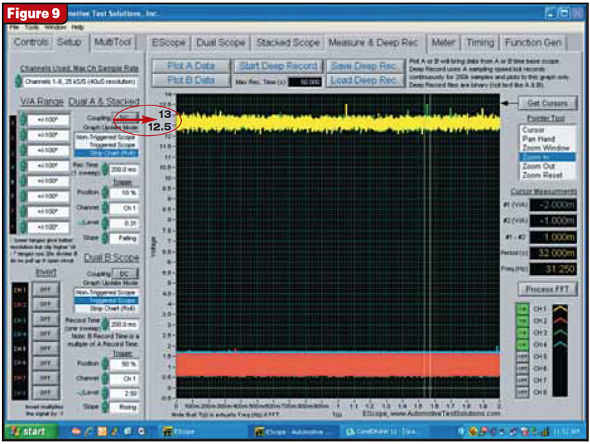
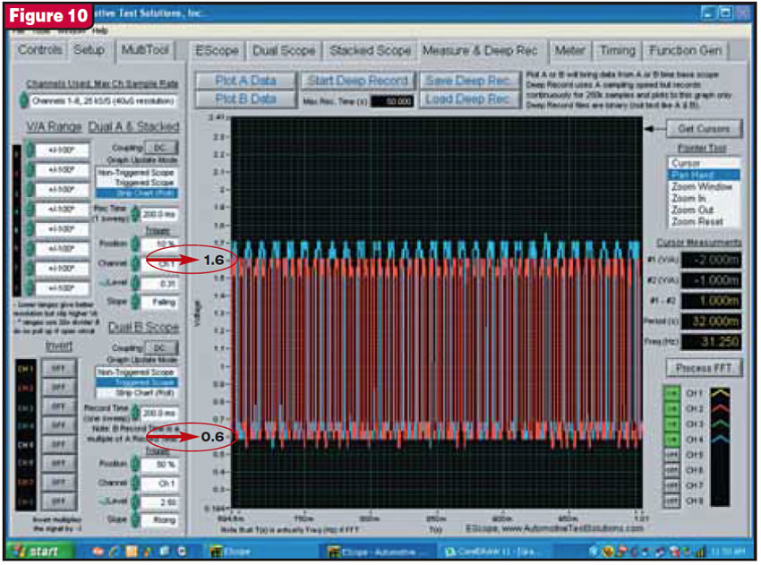
Now we can begin to understand a bit more what the GM technician guide was trying to say. Since this is an Aisin-Warner transmission, it wouldn’t surprise me if the information was originally in Japanese and the problem we have is in translation. A better translation would be that the sensor is supplied with system voltage and uses a 0.6-volt reference point and that the amplitude of the output voltage does not depend on a speed signal (or frequency), as it is fixed at 1.0 volt.
Ultimately, though, both the ISS and OSS are quite easy to diagnose with a meter and scope. Replacing the sensor is even easier with the Saturn Vue. So the view is, sometimes it’s not so bad when it’s bad.
Many thanks to Seth at Aaction Transmissions in Miami for providing the Saturn Vue with the ISS problem.


