Souza Sezz
- Author: Mike Souza, Contributing Editor
- Subject Matter: Joint project
- Issue: Four sensors
Connector pin ID can differ between the Ford & GM versions
There are four internally mounted two-wire Hall-Effect speed sensors found in this shared Ford and GM 10-speed venture (Figure 1). Although all four-speed sensors work the same way, one of them is slightly different than the other three.
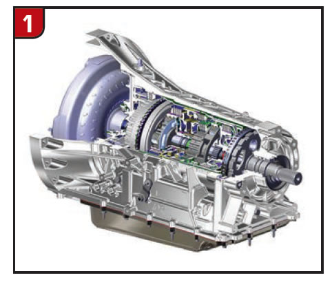
A 9-volt supply from the TCM is sent to all four sensors and a signal from each sensor returns directly back to the TCM. As each speed sensor’s reluctor wheel rotational speed increases, the DC square wave frequency output signal increases. The TCM uses the rpm value from each sensor to control line pressure, shift timing patterns, correct gear ratio and torque converter clutch slip speed. A controlled lockup slip apply will begin shortly after the vehicle takes off while still in first gear. The designation for all four sensors are as follows:
- Intermediate Speed Sensor 1
- Input Speed Sensor
- Intermediate Speed Sensor 2
- Output Speed Sensor
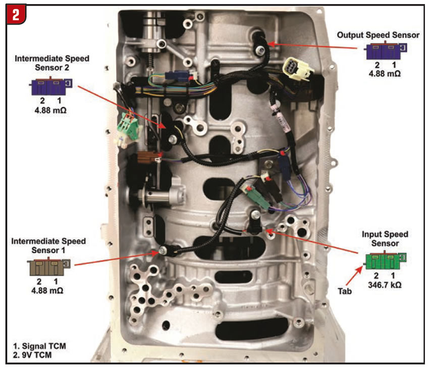
The speed-sensor locations are shown in Figure 2. Notice the alignment tab location for each color connector is different. If the color of the connector is the same the alignment tab will be in the same location. Although there are two blue connectors, their locations are far enough apart to prevent any connection mistakes.
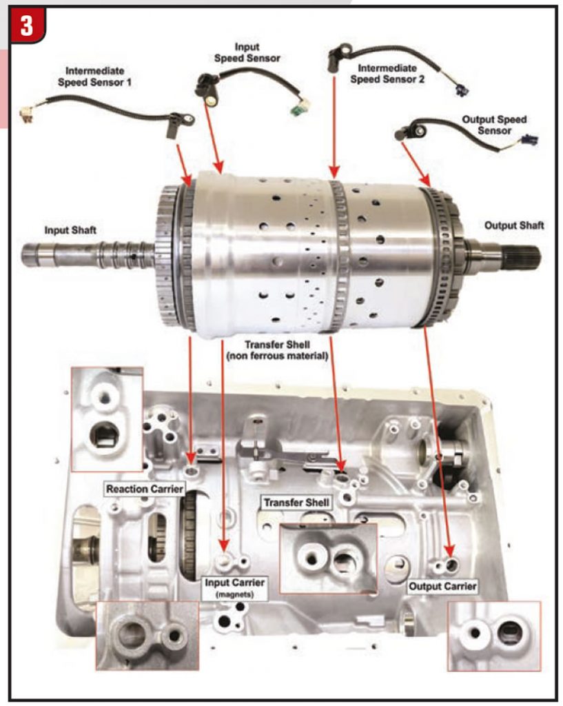
With the speed sensors removed from the case as shown in Figure 3 the drivetrain components being monitored can be seen. The input speed sensor (ISS) is also referred to as the automatic transmission turbine speed sensor (TSS). This sensor monitors a reluctor ring containing 40 evenly spaced magnets bonded in rubber. The reluctor ring is attached (riveted) to the input planet carrier splined to the transmission’s input shaft. The input carrier assembly is located just inside the front section of the transfer shell.
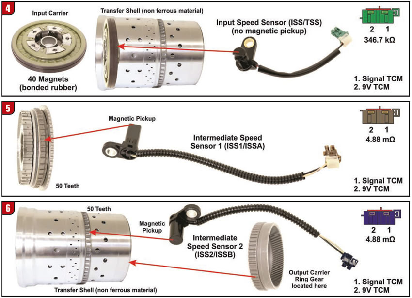
The transfer shell is made of a non-ferrous material allowing the sensor to monitor the magnets through the wall of the shell (Figure 4). This is the only sensor that does not have a magnetic pickup in the tip of the sensor, the magnets are located inside the reluctor ring. The intermediate speed sensor #1 (ISS1) along with the intermediate speed sensor 2 (ISS2) and the output speed sensor (OSS) have a magnetic pickup located in the tip of the sensor. The input speed sensor resistance is approximately 346.7kΩ, whereas the resistance of the other three sensors is 4.88mΩ.

The intermediate speed sensor 1 (ISS1) is also referred to as the automatic transmission intermediate speed sensor A (SSA). The magnetic pickup in the tip of the sensor monitors a 50-tooth steel reluctor ring. The reluctor ring is attached (welded) to the transmission reaction planet carrier internal (ring) gear and 1-2-3-4-5-6 reverse brake clutch hub assembly (Figure 5). The intermediate speed sensor 2 (ISS2), also referred to as the automatic transmission intermediate speed sensor B (ISSB). The magnetic pickup in this sensor monitors a 50-tooth steel reluctor ring attached (pressed) onto the nonferrous transfer shell (Figure 6). The transfer shell has the output carrier internal (ring) gear splined into the rear section of the shell. This signal is used by the TCM to monitor the output planet ring gear rotation (rpm). The fourth sensor is the output speed sensor and only referred to as the output speed sensor.
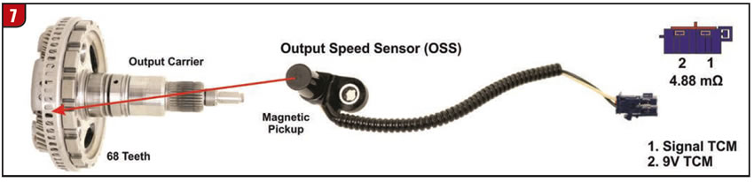
The output speed sensor monitors a steel 68-tooth reluctor wheel that is attached (riveted) to the output planet carrier shown in Figure 7. The reluctor ring and planetary component tooth counts on both the Ford and GM transmissions that we had here at the Seal Aftermarket Tech Center were the same. Therefore, the ratios will be the same although there may be changes from one model to another.
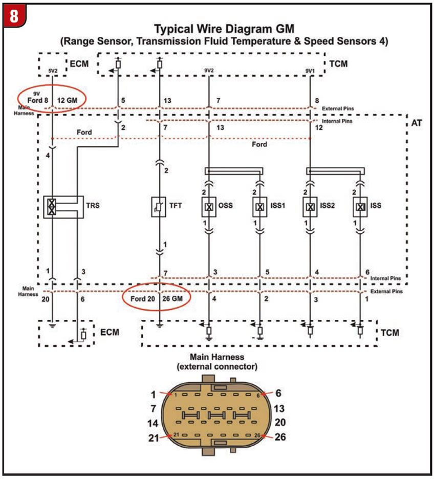
There are differences in connector pin identification between the Ford and GM version of this transmission. The typical wire diagram in Figure 8 reveals the different pin designations between Ford and GM. Well, that about covers the identification and function of all four speed sensors, quite a bit for one transmission. I hope this information will help in diagnosing any speed sensor problems when one of these 10-speed transmissions arrive at your shop. Keep in mind that wire diagrams and connector pin identification can change from one model year to another. Always verify the information for the vehicle you are repairing with factory information whenever possible. The information presented in this article was derived from factory information and considered correct. We will try to keep you up to date on any future changes with this transmission as more information becomes available.
In our next issue of Transmission Digest we are going to cover the new unique sump (pan) filtering system and strategy found in this transmission. Thanks for reading!


