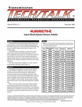


A new turbine input-shaft-speed (ISS) sensor has been added in some limited models beginning with the 2006 model year and expanded to additional plat-forms for 2007. Refer to the chart in Figure 1 for model usage.
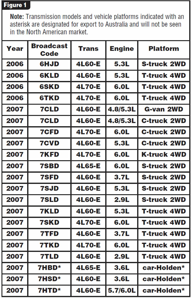
The ISS-sensor assembly is a three-wire Hall-effect sensor that is mounted internally to the oil-pump assembly (see Figure 2).
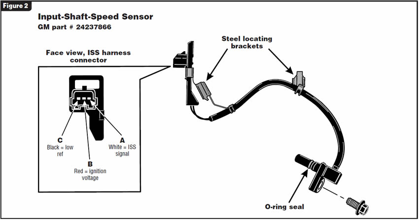
The sensor uses the rotor teeth on the turbine input shaft to generate a digital voltage signal of varying frequency that corresponds to the rotational speed of the input shaft (see Figure 3).
This also required the addition of a new internal wire-harness assembly (see Figure 4).


The ISS-sensor signal is an input to the control module (PCM or TCM) that will be used to better monitor and control line pressure, shift patterns, torque-converter-clutch slip speed and gear ratios. This component will allow the 4L60/65/70-E transmissions to enable use of computer instructions (algorithm) related to shift energy, abuse torque management and provide much improved diagnostic capabilities.
Note: The new turbine input-shaft-speed sensor was gradually phased into production, and certain design-level criteria had to be followed. The following information is intended to provide a general outline of the stages involved to implement the use of the ISS sensor.
Effective Feb. 1, 2005, the oil-pump cover uses a new-design TCC valve with a single spring (see Figure 5).
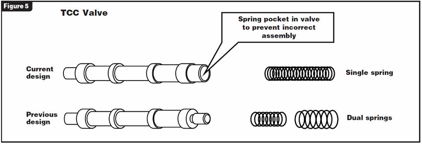
Simplifies the assembly process, eliminates the possibility of springs becoming bound or bent and reduces material cost.
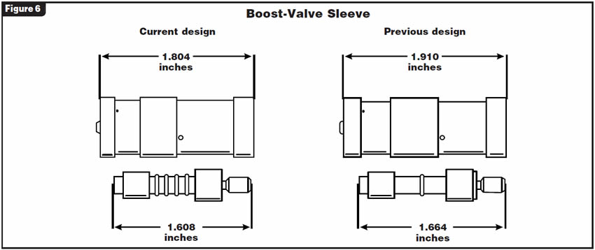
Effective March 7, 2005, the oil-pump cover uses a more-compact boost valve and sleeve (see Figure 6).
The snap-ring groove for the boost-valve sleeve now is 2.57 inches from the bottom of the bore, compared with 2.68 inches for the previous design (refer to Figure 7). The bore length for the boost-valve sleeve and snap ring has been reduced by 0.106 inch.
Necessary to prepare for the new ISS-sensor assembly that will be packaged into the pump cover.
After July 16, 2005, the pump-cover casting was modified to situate the ISS connector. This modification removed metal directly below the pressure-regulator valve and boost-valve-sleeve bore and extended a cast wall inward. The internal TCC-release passage also was modified at this time. The mounting holes for the ISS sensor have not yet been machined into the oil-pump cover (this also is shown in Figure 7).
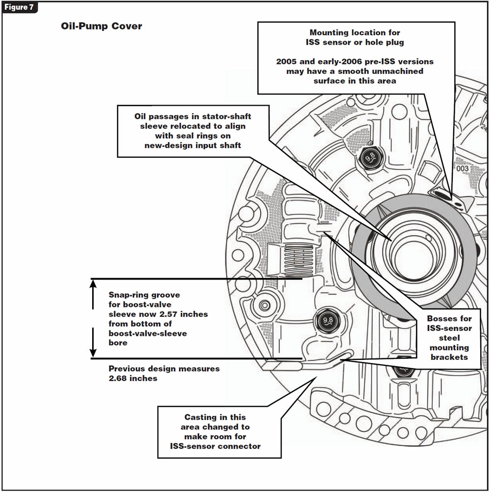
Establishes a mounting point for the ISS-sensor connector, creates a mounting surface for the ISS-sensor assembly and will enable positioning of the ISS-sensor assembly to target rotor teeth on the turbine input shaft.
Changes to the oil-pump cover also affected the stator shaft and stator-shaft sleeve so as to correlate with oil passages within the oil-pump cover. At the same time, the grooves for the turbine-shaft oil-seal rings were moved inboard toward the rear of the unit about 0.190 inch to create an area to accommodate 15 rotor teeth.
To correlate with changes in the stator shaft and sleeve assembly.
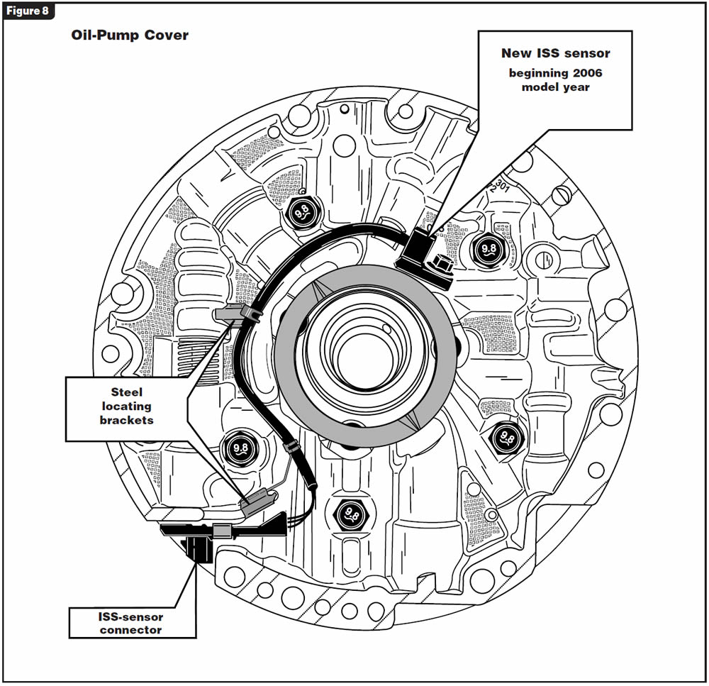
Late in 2005 and early in the 2006 model year, some pre-ISS-sensor models still may not have the ISS-sensor mounting holes machined into the cover. This will be evident as a smooth un-machined surface. As models with the ISS sensor were introduced, the machining took place and the ISS sensor was added (see Figure 8).
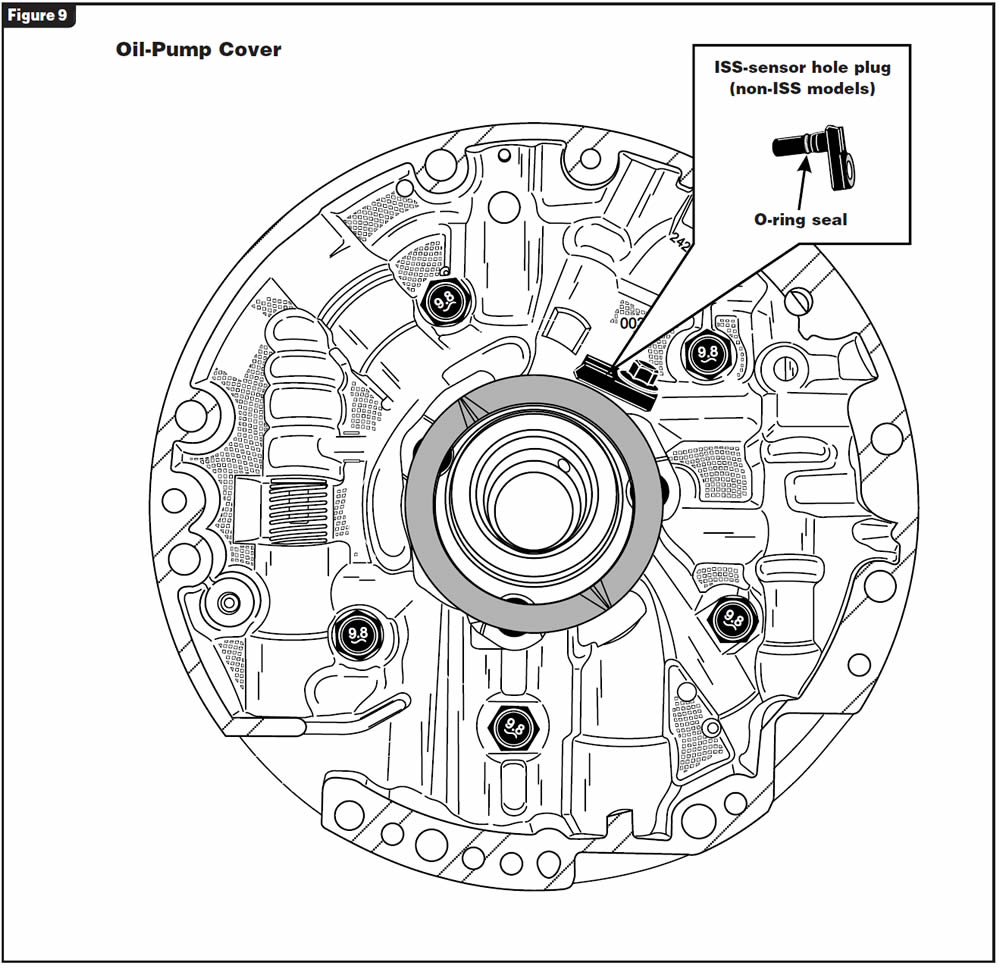
For models without the ISS sensor, a hole plug is used in place of the ISS-sensor assembly (see Figure 9).

Unit identification – Refer to the chart in Figure 1 for a list of transmissions and vehicle platforms known to use an ISS sensor at the time of this printing.
Input-shaft-speed sensor – The ISS-sensor assembly, as shown in Figure 2, is internal to the transmission. Operation of the ISS sensor should be thoroughly evaluated with a scan tool to monitor shaft speed before transmission removal for any repairs. Because of the ISS-sensor circuitry design with its internal integrated-circuit chip, measuring the internal resistance is not beneficial; therefore, no internal resistance values have been made available.
Improper converter-clutch operation or possible converter drain-back concerns may result if the O-ring seal is damaged or omitted during servicing of the ISS sensor.
The steel locating brackets are necessary to keep the ISS-sensor wiring from coming in contact with the rotating reverse-input-clutch housing. These brackets push-fit onto aluminum bosses that are cast into the oil-pump cover.
At the time of this printing, the OEM part number for the ISS-sensor assembly is 24237866.


Turbine input shaft – The turbine input shaft, as shown in Figure 3, now has 15 rotor teeth added to trigger the ISS sensor. The oil sealing-ring grooves have been relocated inboard toward the rear of the unit about 0.190 inch when compared with the previous design. Turbine input shafts in some pre-ISS models may have the rotor teeth machined in place. Since this was a manufacturing option, some do not. For this reason, you must take great care when replacing the input-clutch housing and turbine-shaft assembly. A measurement from the front-most oil sealing-ring groove to the base of the input shaft where it is pressed into the clutch housing must be taken and compared with that of the replacement component to ensure compatibility, or else transmission failure will be the result.
Internal wire harness – The internal wiring harness shown in Figure 4 contains additional circuits for transmissions equipped with ISS sensors and can be identified easily by the black 20-way pass-through connector. Transmissions without the ISS sensor use the previous-design harness, which has a light-gray connector. The ISS-sensor circuit shares pin position E (Ckt 839) for ignition-feed voltage. This is a pre-existing circuit and is spliced internally to supply power to the ISS sensor. The additional pin terminals are K (Ckt 1230) for ISS signal and also V (Ckt 1231) for low reference.
At the time of this printing, the OEM part number for the new internal wire harness for transmissions equipped with the ISS sensor is 24234121.
TCC valve – The new-design TCC valve uses a single spring and is shown along with the previous-design-level valve with dual springs in Figure 5. The new valve incorporates a spring pocket to prevent incorrect installation by allowing the spring to be inserted into only the pocket end of the valve. Components of the previous and current designs may not be intermixed. However, the current-design TCC valve and spring can be used to back-service the previous design level.
Boost valve and sleeve – The boost-valve sleeve and its corresponding valve have been made shorter overall (see Figure 6). No components of the current and previous designs may be intermixed nor interchanged as an assembly in place of the other. There are two versions of the current-design boost-valve and sleeve assembly, with different valve-land dimensions, for standard and high-performance use. The pressure-regulator valve, pressure-regulator-valve spring and pressure-regulator-isolator spring remain the same as the previous design.
Oil-pump cover – Figure 7 outlines the changes to the oil-pump cover and stator shaft. Great care is necessary if the oil-pump cover and/or stator shaft are to be replaced. This is because of the many changes in the oil-pump-cover casting and corresponding stator shaft sleeve oil passages. These pieces must be compatible with the turbine input shaft being used or transmission failure will be the result.
The boost-valve sleeve and pressure-regulator valve cannot be serviced from the sump area on units equipped with an ISS sensor because of the location of the ISS-sensor connector (see Figure 8). This operation will require removal of the transmission and oil-pump assembly.
Pre-ISS or non-ISS models equipped with an ISS-sensor hole plug as shown in Figure 9 will still allow access to the boost-valve sleeve and pressure-regulator valve from the sump. If the O-ring is damaged or is omitted from the ISS hole plug, improper converter-clutch operation or converter drain-back may occur. Failure to install the ISS hole plug if required will result in low or no converter charge and no movement.
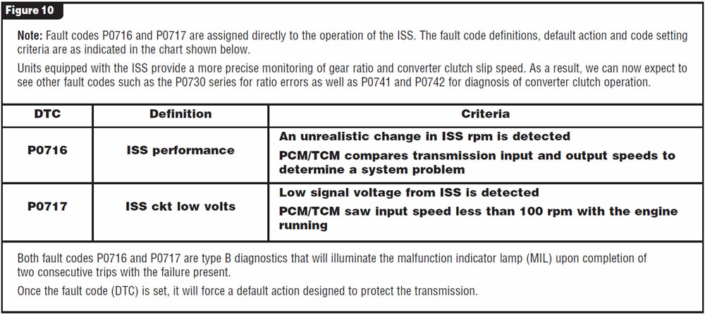
Fault codes – Refer to Figure 10 for information on diagnostic trouble codes.


November 2007 Issue
Volume 24, No. 11
- 4L60/65/70-E: Input-Shaft-Speed Sensor Added


