Torque Converter Tech Tips
- Author: Ed Lee
Since the early days of torque converters, the contact surface between the stator cap and turbine hub has been a high-wear area. The first torque converters used aluminum stator caps that ran against the cast-steel turbine hubs. Material loss due to wear on the stator cap needed to be compensated for when the converter was being rebuilt. Most rebuilders viewed the wear as normal and dealt with it by using selective thrust washers and wear plates.
Then came the early rear-wheel-drive Chrysler and early front-wheel-drive Mitsubishi converters. The severe wear on their stator caps forced converter rebuilders and designers to take another look at the problem, and the search for a solution began. Some manufacturers dealt with the problem by installing thrust washers between the stator cap and turbine hub; others opted to change the material of the stator cap.
Installing the thrust washers and changing to a phenolic material were both successful in some instances, but for the most part wear was still an issue. Installing a bearing between the stator and turbine hub seemed like the best option, but limited space and the need for a tall piloting area kept the use of a bearing to a minimum. The tall piloting area was necessary because the internal forces of the converter keep the stator and turbine separated except during deceleration.
At this point most engineers were assuming that the stator-cap material needed to be upgraded, and that is where they focused their research. However, we all know what assuming does.
The testing
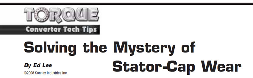
In the search for a better material, one engineer was testing stator caps on a machine that was built for testing thrust washers. It was simply a matter of replacing the phenolic washer seen in Figure 1 with the stator cap and wear plate to be tested. The machine was capable of varying the rotating speed and the pressure load that the stator caps would be subjected to. The tester also could control the flow rate (gallons per minute) of the fluid that lubricated the contact area and monitor the temperature of the oil at the wear surface and in the sump.
The aluminum stator cap common in the early A4LD converters and a like-sized-diameter wear plate were chosen for the test. Test parameters were kept as close to actual converter conditions as possible, and the machine was set into motion. The idea was to use the wear of the first test cap as a baseline and compare that wear with that of other materials tested under the same conditions.
The problem was that the test cap would not show any wear as long as sufficient lube was present at the wear surface. The machine kept a constant 2-gpm flow of lubricant to the wear surface. The engineer tried increasing the speed and even increased the load from 500 to 625 psi and still did not get any appreciable wear on the part.
He also observed that the temperature at the wear surface stayed constant. He was beginning to think that the wear to the original stator caps in the field might be caused by a lack of lube, but he could not see how that would be possible. Out of frustration he took the wear plate out of the machine and scuffed the smooth surface on the concrete floor with his foot before returning it to the machine. The tiny scratches on the wear plate now wore the stator cap down in 20 minutes.
Then the engineer had a bright idea. He had eight wear plates machined with different surface finishes that ranged in roughness average (RA) from 12 to 36. The lower the RA number, the smoother the surface. The engineer repeated the test with the modified wear plates and got very different results.
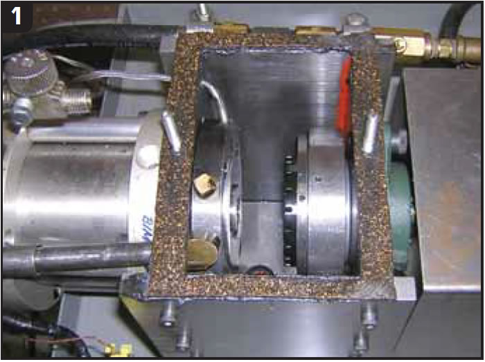
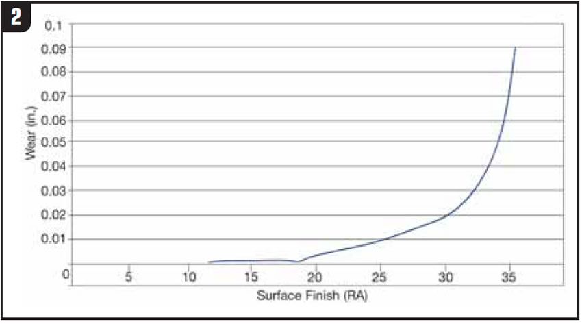
The engineer now observed that the wear to the stator cap was directly proportional to the RA of the mating surface. From 6 to 20 RA the increase in wear was very little, but above 20 RA the wear rate increased dramatically. In fact, from 20 RA to 35 RA the wear rate of a stator cap doubles. The graph in Figure 2 shows how dramatically wear begins to increase as surface finish exceeds 20 RA. You can easily see that the stator cap on the left in Figure 3 has plenty of material left after being run against the 18-RA wear plate shown above it. Compare that with the remaining material on the stator cap on the right, which ran on the RA-36 wear plate.
The bottom line
The wear test on the aluminum stator caps proved that a surface finish of 20 RA or less is necessary for extended stator-cap life. Another wear test done by a different facility at a later date was even more conclusive. This new test proved that a surface finish of 13 to 16 RA was the best range for optimum wear.
The new test had two additional interesting findings. The first was that the mating wear surface can be too smooth. When the wear-surface finish is smoother than 6 RA, the oil retention begins to diminish and the wear rate begins to increase. This should not be a problem, because it is difficult to achieve a surface finish smoother than 6 RA in most converter shops.
The second interesting finding was that although material selection for specific applications is still critical, the correlation between surface finish and wear applies equally to all materials. The wear to both aluminum and phenolic stator caps was good when the mating-surface finish was correct, and the wear rate of each increased as the surface finish got rougher. This was also true when the stator cap had a brass or bi-metal washer attached.
Getting the perfect surface
Ideally, a profilometer would be used to measure the RA of a machined surface. Although a profilometer may be too expensive for the average converter shop, the average shop can still get the correct finish. Chuck the turbine hub in a lathe, and if the surface is already smooth, finish-polish the surface with 1,000-grit emery paper. If the surface is not already smooth, start with 150-grit emery paper and then finish with 1,000-grit emery paper. This will give you a surface finish that is smoother than the recommended 20 RA and should extend your stator cap life.
Metal thrust washers
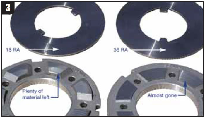
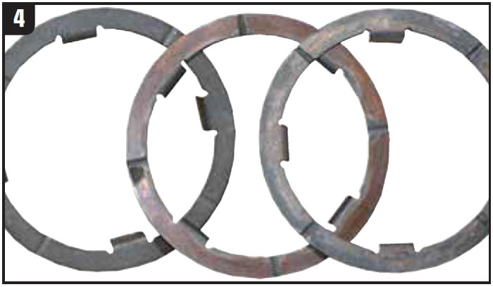
The gray material on the exterior of most metal thrust washers is actually a micro-fine polishing compound. The compound polishes the surface of the mating part to extend the life of the thrust washer. As the polishing compound does its job, it disappears from the surface. The thrust washers in Figure 4 appear to show varying degrees of wear, but that is not the case. Looking closely at depth of the oil grooves, you will see that washer thicknesses are the same. The different appearance is due to the amount of polishing compound that is missing. The thrust-washer manufacturers use this compound to improve the surface finish of the mating part. The manufacturers have understood the relationship between surface finish and wear for years.
Special thanks to Sonnax engineer Scott Jackson, whose technical expertise and diligent testing made this article possible.

Ed Lee is a Sonnax technical specialist who writes on issues of interest to torque-converter rebuilders. Sonnax supports the Torque Converter Rebuilders Association. Learn more about the group at www.tcraonline.com.


