Torque Converter Tech Tips
- Author: Ed Lee
Part 2 in a four-part series on torque-converter modifications
Last month we reviewed the results of chassis dyno testing done by Sean Boyle’s students in the automatic-transmission class at Southern Illinois University. Four modified torque converters were evaluated. The testing was done on an MD-250 Mustang Chassis Dyno, and the test vehicle was a stock 2000 Dodge Durango RT equipped with a 5.9-liter gas engine and a 46RE transmission.
The converter replacement was the only change made to the vehicle, and only one modification was done to the converter for each test. In Part I of this series, converter A had a modified stator – 0.250 inch had been machined from the impeller side of the stator, and this modification lowered the stall of the converter. The test vehicle responded favorably to this modification, which would have helped the vehicle’s towing capabilities and probably enhanced fuel economy.
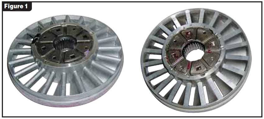
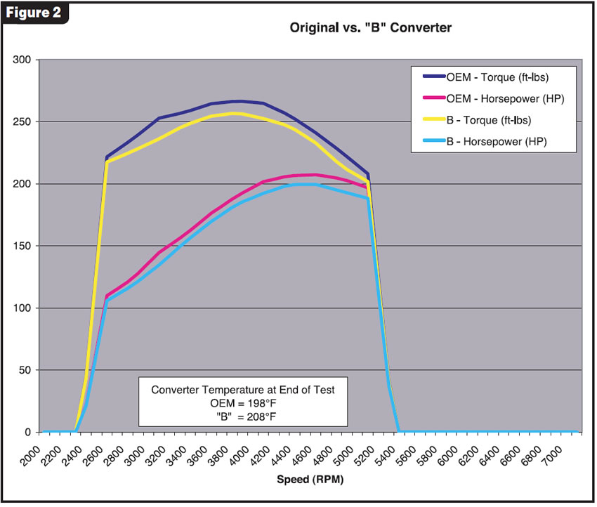
This month we look at how converter B tested. Converter B also had a modified stator. The difference is that in this converter, 0.175 inch was machined from the turbine side of the stator. (Figure 1 shows the modified stator below an OEM stator.) This particular modification is popular on performance converters to increase stall. Since no brake stall test or timed acceleration test was performed for these evaluations, there was no measurable increase in stall. When you compare the graphs of the OEM converter vs. modified converter B in the overlay in Figure 2, you can see that the horsepower and torque readings for both converters start around 2,300 rpm. You also can see that the horsepower and torque readings of the modified converter B remained below the readings of the OEM converter throughout the run. When you do line-by-line comparisons of the OEM vs. the modified B converter at specific engine speeds, you see dramatic differences (see Figure 3).
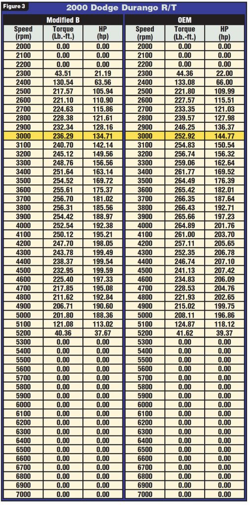
The biggest difference occurs at 3,000 rpm. The OEM converter was outperforming the modified converter by 16 horsepower and 10 lb.-ft. of torque at that speed break. The difference in performance remained at least 9-10 hp better for the OEM converter throughout the runs.
This is where the trade-offs mentioned in Part I come into play. The wide-open-throttle horsepower tests are great for evaluating the horsepower and torque that are being delivered to the ground. However, they do not show the acceleration values of the vehicle. By machining the turbine side of the stator, you are increasing the distance between the turbine and stator, and this will raise the stall of the converter. This can be very beneficial if the power-band level of the engine has been enhanced and the converter stall is increased to meet this level of performance. But as you can see from the graphs and charts, better acceleration on a stock-engine application comes with a price. The inefficiency that helped create the higher stall decreases horsepower and torque during normal operation.
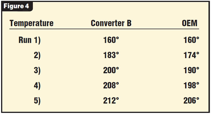
Inefficiency also is related to an increase in temperature. By the third run, the modified converter was 10°F hotter than the OEM converter. When you consider that the total run time – including the 30-second delays between runs – was less than 21⁄2 minutes, that increase in temperature is significant. Prolonged use of a vehicle with this modification would normally require additional cooling.
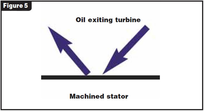
Part of the inefficiency of the converter comes from the modification itself. The stator blade of the OEM stator is wider and rounded at the turbine side (see Figure 1). This helps to redirect the flow of oil from the turbine to the impeller. The modified stator has a flat machined surface exposed to the oil exiting the turbine. The oil that strikes this surface will be deflected back toward the turbine, slowing its rotation.
Evaluate all the advantages as well as the trade-offs when you are considering a modification to a converter. The end result should be the best possible compromise for your application.
Next month: Evaluating another way to increase stall.
Special thanks to Sean Boyle and students Zack Emberton, Ross Rohlman and Luke Davies at Southern Illinois University for their help in compiling this information.

Ed Lee is a Sonnax Technical Specialist who writes on issues of interest to torque converter rebuilders. Sonnax supports the Torque Converter Rebuilders Association. Learn more about the group at www.tcraonline.com. ©2007 Sonnax Industries Inc.


