Torque Converter Tech Tips
- Subject: Overheating, 740 codes
- Unit: 4L80-E
- Vehicle Application: 1992 GM 3500 4 x4 pickup; 2004 GM 2500 pickup; GM 3500 van
- Essential Reading: Rebuilder, Diagnostician
- Author: Ed Lee
4L80-E overheating/740 codes
Try to imagine the difficult job tech-line technicians have. They are asked to decipher bits and pieces of information that may not be accurate and then come up with the correct answer. The information the technicians collected for the following two scenarios seemed to be as different as night and day. The information even originated in different countries. The amazing thing about these different complaints and symptoms was that they all had the same root cause.
Vehicle 1
Vehicle 1 was a 1992 GM 3500 4×4 equipped with a utility body. The vehicle would not move forward and was towed to the shop. Upon teardown, the forward clutches were found to be completely burned up, and a complete overhaul including a rebuilt torque converter was recommended. The customer approved the overhaul and asked that a temperature gauge be installed at the same time. The repair seemed to be progressing routinely until the R&R technician noticed that the temperature gauge had climbed to 190°F while the vehicle was still on the lift. At first the gauge was thought to be defective, but a replacement gauge showed the same temperature. The technician suspected a restricted cooler, and a flow-monitoring device was installed before the vehicle was road tested. On the shop’s usual six-mile test loop, the vehicle had a good cooler-flow rate of 3.2 gallons per minute (gpm) but reached transmission temperatures in excess of 285°F (Figure 1).
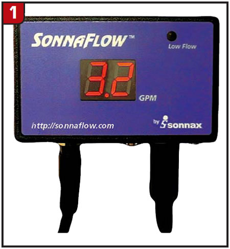
The only time the temperature would go down was on a downhill coast, but that was only a 15°-20° drop. The technician even burned his hand when he was removing the flow-monitoring device. After an external cooler was added, the temperature was about 20°F cooler but was still considered excessive at 265°F. At this point the converter was removed for evaluation.
Vehicles 2 and 3
The second scenario involved two GM vehicles. One was a 2004 2500-series equipped with a 6.0-liter engine. The second was a 3500-series cube van equipped with the same-size engine. The vehicles had 164,000 and 178,000 kilometers, respectively. Both vehicles had their 4L80-E transmissions overhauled and their converters replaced with remanufactured units, and both vehicles were returned later because of 740 codes. When scan tools were placed on the vehicles, they recorded TCC slip rates of 50-80 rpm under normal driving conditions. When any additional load was placed on the vehicles, such as hilly terrain or towing, the slip rates would climb to more than 250 rpm. After the normal in-vehicle checks – including cooler-flow measurement – yielded satisfactory results, the converters were removed for evaluation.
Evaluating the converters
The overall height and endplay of the converters were checked before the converters were cut apart. The overall height was correct for all three converters, and although the endplay was on the high side at 0.025 inch (normal is 0.005-0.010 inch), it was not off enough to raise any red flags. When the converters were cut apart, the internal clearances and clutch-release clearances were checked. The internal clearance was well within the proper parameters (0.100-0.110 inch), but the clutch-release clearance for the first converter was zero and the other two converters were at minus 0.005 inch. Normal release clearance is 0.030-0.035 inch.
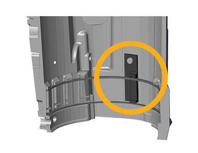
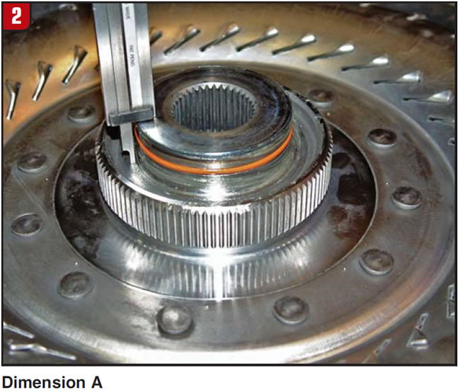
How is a “negative clearance” possible? In this design, a clutch-release-clearance target of 0.030-0.035 inch (the piston travel from full apply to full release) is adjusted separately from the endplay. Clutch-release clearance is calculated on the basis of two dimensions. Dimension A is the distance between the leading edge of the turbine hub and the surface the piston will rest on when it is in the fully released position (Figure 2).
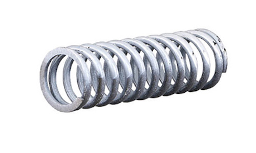
Dimension B is the distance between the lockup-piston seal-bore edge and the front thrust washer (Figure 3). This represents the piston’s location in the fully applied position.
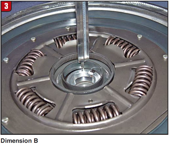
Clutch-release clearance is the difference between the two measurements, or A minus B. If B is larger than A, then the negative number is “negative clearance.” There is no clutch-release clearance at all, and the negative dimension is actually how far the turbine hub is being held back from its normal position of contacting the cover.
The causes
What caused the zero and negative clearances in the three converters? All three converters originally had 0.040-inch friction material, and all were rebuilt using 0.075-inch friction material during the rebonding process. The 0.035-inch difference in the thickness of the friction material caused the loss of clutch clearance. One way to resolve the clearance issue would have been to machine 0.035 inch from the reaction surface of the cover. For the three vehicles discussed here, the issue was resolved by returning to the original 0.040-inch-thickness friction material.
What caused the overheating and 740 codes? Inadequate clearance prevented sufficient fluid flow between the cover and piston in the release position. The overheating converter in the first vehicle simply could not pass enough fluid internally, and the temperature gauge showed it.
Inadequate clearance took its toll on the 740-code converters as well. Inadequate fluid flow and dragging of the clutch material in the release mode deteriorated the lining to the point that it could no longer function properly during application.
Diagnostic Differences
The diagnostic information provided for these vehicles was different because the technicians used different diagnostic tools. Vehicle #1 was diagnosed with the help of a temperature gauge and a flow monitoring device. In this case, a catastrophic failure was averted without ever knowing that the converter had a higher-than-normal slip rate. Vehicles #2 and #3 were diagnosed with the help of a scan tool. Catastrophic failures were averted in these cases, without the knowledge that the transmissions were overheating. After all three converters were replaced with converters with the correct clutch release clearance, the temperature of vehicle #1 never went higher than 150°F, and the slip rates on the other two vehicles returned to normal.

Ed Lee is a Sonnax Technical Specialist who writes on issues of interest to torque converter rebuilders.
Sonnax supports the Torque Converter Rebuilders Association. Learn more about the group at www.tcraonline.com.
©Sonnax2010