More Centerline Issues - Transmission Digest

More Centerline Issues

Maintaining the proper centerline during the torque-converter rebuild process is very important. How well the centerline was maintained during the process can be measured by how much balance weight needs to be added at the end of the process.

More Centerline Issues

Torque Converter Tech Tips

Author: Ed Lee

Torque Converter Tech Tips

  • Author: Ed Lee

Maintaining the proper centerline during the torque-converter rebuild process is very important. How well the centerline was maintained during the process can be measured by how much balance weight needs to be added at the end of the process.

The original-equipment manufacturers (OEMs) do a good job of maintaining the centerline when they build the torque converter. If the converter is indexed properly, the aftermarket rebuild should require about the same amount of weight to rebalance. If the converter requires significantly more weight to rebalance, the rebuild process should be inspected for centerline issues.

Balancing basics tell you that you are adding weight on one side of the converter to offset a heavy spot on the opposite side of the converter. If you haven’t added any weight to the converter, where did the heavy spot come from? The answer is that either you are compensating for weight that was removed from the converter during a machining process or you are compensating for an off-center condition.

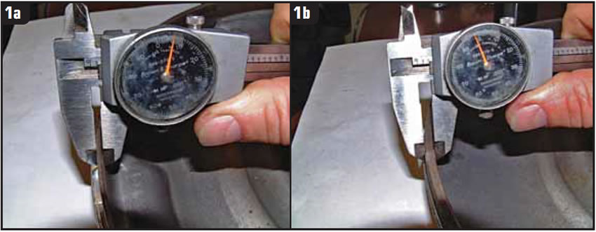
The centerline issues that affect the balance process may start as early as the parting procedure. When a converter is not piloted properly while being cut open, more metal must be removed from one side of the cover or impeller to separate the unit.

In Figure 1, a Chrysler pilot sleeve was mistakenly used when this GM converter was parted. The loose piloting allowed an off-center condition that resulted in one side of the cut converter being much thinner and lighter than the opposite side. If these components are reused, the converter will require more weight to rebalance.

The centerline issues continue into the preparation processes. The cover and impeller need to be centered properly when they are machined for clearance. If the impeller is going to have a new hub welded in place, efforts must be made to keep the new hub concentric with the centerline. Even a few thousandths inch off center at any step will mean several grams of extra weight to rebalance.

The welding and balancing processes are next to come under scrutiny, and both have centerline issues that involve the converter pilot. The turntables on the welder and balancer each rely on some sort of collet or sleeve to center the converter. Any wear to the collet, sleeve or the pilot itself will dramatically affect the balance process. The amount of imbalance will vary with the weight and diameter of each converter.

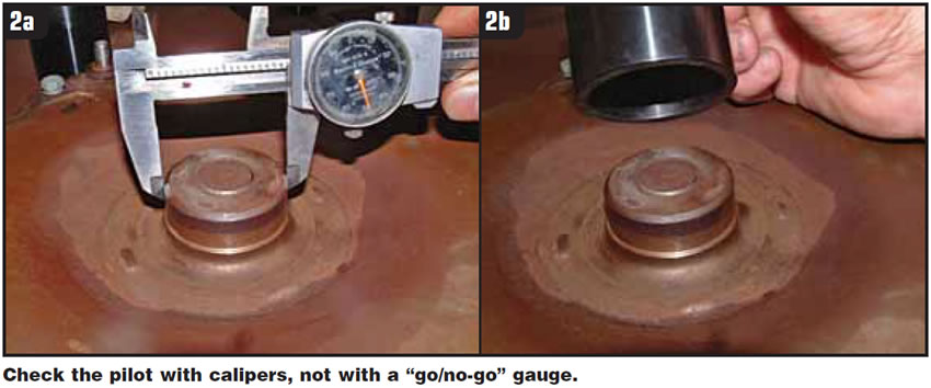
For example, a 45-pound converter 12 inches in diameter will need almost 31/4 grams of added weight for each 0.001 inch that the converter is off center. The heavier and larger-diameter converters will need even more weight to compensate for any off-center conditions. For accuracy, each pilot should be measured individually in at least two places with either calipers or micrometers. You should never rely on a go/no-go gauge to check a pilot.

Following your shop-equipment manufacturer’s routine-maintenance schedule is also very important. This includes checking the runout on your welder and balancer at regular intervals. Tools and equipment that are worn out or are out of calibration can cause multiple issues.

Rebuilding a torque converter is a lot like building a house. If you start with a good foundation, you will have a much better chance of ending up with a quality product. If you pay attention to keeping all the components in a torque converter concentric, perpendicular and parallel as required, you will find that you won’t have to compensate by adding large amounts of balance weight to your finished product.

Ed Lee is a Sonnax Technical Specialist who writes on issues of interest to torque-converter rebuilders. Sonnax supports the Torque Converter Rebuilders Association. Learn more about the group at www.tcraonline.com.

You May Also Like

Sherlock Holmes Approach to an AB60 No-Move Situation

The effectiveness in diagnosing automatic transmission malfunctions is an art form. Although there are similarities among the wide varieties of transmissions on the road, each transmission has its own peculiarities. Aside from having mechanical, hydraulic, and electrical hardware systems to contend with, software/programming issues and various vehicle platforms make diagnostics much more difficult.  Using scopes provides

ab60

The effectiveness in diagnosing automatic transmission malfunctions is an art form. Although there are similarities among the wide varieties of transmissions on the road, each transmission has its own peculiarities. Aside from having mechanical, hydraulic, and electrical hardware systems to contend with, software/programming issues and various vehicle platforms make diagnostics much more difficult. 

GM 6T40 Pump Identification Guide

The 6T40 was introduced in 2008 for General Motors front-wheel-drive cars in the Chevrolet Malibu and has gone through several changes throughout its three generations, specifically in the pump area. The 6T40 is closely related to the more lightweight 6T30 and the heavier duty 6T45 and 6T50. Generation one started phasing out during the 2012

Seeing the Forest AND the Trees

They say that the proverbial phrase “I couldn’t see the forest for the trees” means that a person or organization cannot see the big picture because it focuses too much on the details. Related Articles – 4L60E Harsh 1-2 Shift – TASC Force Tips: Diagnosing 8L45 & 8L90 Shift Complaints – TASC Force Tips: Hydraulics

The Manifold Pipeway

The Honda six-speed transmission has been on the bench of many specialty shops for one reason or another (figure 1). But, for those of you who have yet to lay your hands on one, mounted on the upper side of the unit is one of the largest, if not the largest solenoid and pressure switch

8L90 Vacuum Testing

Below are the diagrams for vacuum testing GM 8L90 transmissions. Note: OE valves are shown in rest position and should be tested in rest position unless otherwise indicated. Test locations are pointed to with an arrow. Springs are not shown for visual clarity. A low vacuum reading indicates wear. For specific vacuum test information, refer

Other Posts

Critical Wear Areas & Vacuum Test Locations for FORD 6R80/6R100

Note: OE valves are shown in rest position and should be tested in rest position unless otherwise indicated. Test locations are noted with an arrow. Springs are not shown for visual clarity. Low vacuum reading indicates wear. For specific vacuum test information, visit www.sonnax.com. Related Articles – Hydraulics Fundamentals: Shift & Relay Valves – Another

Hydraulics Fundamentals: Shift & Relay Valves

Shift valves and relay valves share a lot of the same duties. This article is one of a series by Sonnax exploring how valves and hydraulic circuits work and what results when they quit functioning correctly.

Another 62TE ‘No-Move’ Possibility

Most seasoned techs have several quick diagnostic steps they take when faced with a transmission malfunction. The type of problem and transmission determines which steps to take. For example, a “no-move” condition. Related Articles – Ford 8F24 mechanical diode failure – Ford 8F35 maintenance tips: Planetary failure and no-pressure conditions – Don’t fear customer complaints about

Hydraulics Fundamentals: Clutch Regulator Valves

Knowing how these circuits work and the slightly different variations that the manufacturers utilize should pinpoint any valve body-related issues