


A typical rebuild was done on a 2006 Ford Fusion. The vehicle came equipped with a 2.3L engine and an FNR5 transmission. The initial complaint was slipping third and fourth gears. The 1-2 upshift was nothing to rave about either.
During disassembly, the 2-4 band and direct frictions were found to be smoked. Fortunately, there was no hard-part damage, so it was basically a soft overhaul, with one exception: The servo-pin bore in the case was worn somewhat, which is a common problem. When the servo-pin bore wears, it allows servo-release and direct-clutch apply pressure to escape, resulting in a burnt band and clutches.
The transmission was completely rebuilt and the case servo bore was repaired by reaming the bore and installing a service bushing. The tool kit is available from Northland Transmission and will accommodate both the FNR5 and 4F27E.
The transmission was reinstalled and road tested, and initially everything worked well. The 2-3 and 3-4 upshifts were normal, and at first, 5th gear worked well, but then things started to go south. Fifth gear became erratic, almost as though the “F” solenoid were misfiring or the shift valve were sticking. The computer signals were checked and found to be OK, the auxiliary valve body was pulled and the solenoid was tested. Everything seemed to be intact.

Once everything that would normally cause the problem was checked and ruled out, drastic measures were called for. So, as a last resort, look at the oil schematics to solve the problem. After a review of the diagrams, it became apparent what the culprit was: wrong valve-body gaskets.

The FNR5 is a five-speed version of the 4F27E, although the Mazda/Ford five-speed models are more comparable than the four-speeds. The basic four- and five-speed models look, smell and feel the same. As with other transmission types that evolved from a four-speed to a five-speed, the FNR5 is little more than a
4F27E with an underdrive planet section and auxiliary valve body. The unit is comprised of an underdrive planet set, underdrive direct-clutch assembly, reduction brake and one way clutch (OWC). The reduction brake is applied in reverse and first through fourth gears. The reduction direct clutch is applied in fifth.
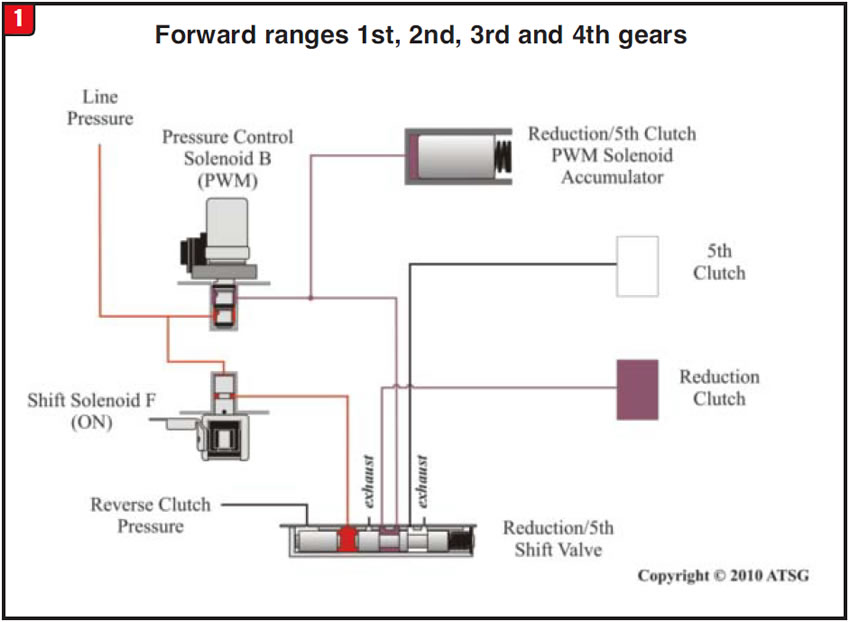
Currently, OEM oil schematics are not available; however, the folks at ATSG did produce certain schematics to aid in diagnosis (figures 1 & 2). Figure 1 illustrates how the under-drive section and auxiliary valve body operate in first through fourth gears. Note that the reduction/fifth shift valve is moved to the right by pressure from the “on” shift solenoid F. In this position, oil pressure from the PCS B solenoid can apply the reduction brake, thus providing first through fourth.
Once the computer deter-mines fifth gear is needed, shift solenoid F is turned off. When the solenoid turns off, shift-valve apply oil exhausts, allowing the valve to stroke to the left (Figure 2). With the valve in this position, oil pressure can switch from the reduction brake to the reduction direct clutch. So what is responsible for the erratic no fifth
gear?
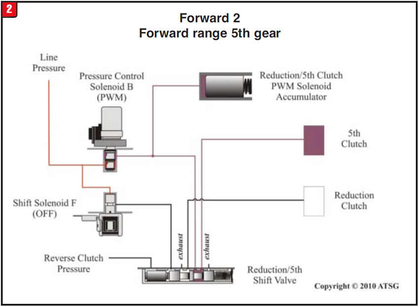
As illustrated in figures 1 and 2, the reduction/fifth shift valve has an extra oil passage at the left side of the valve for reverse apply. When the transmission is shifted into reverse, the reduction/fifth shift valve moves to the right, as is the case in first through fourth gears. If, for some reason, the reverse passage was blocked, reverse would still work because of the F-solenoid “on” pressure moving the valve to the right. A blocked passage would, however, cause another problem: no exhaust capability.
Since valves and valve bores are not airtight, oil can move past a valve and fill the end cavity, which will prevent movement. With the shift valve to the right, fifth gear is not possible. So how can the oil passage get
blocked?
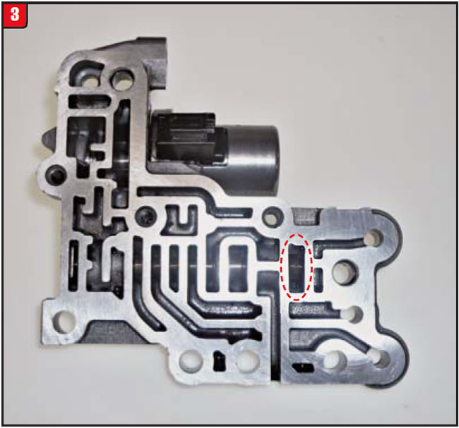
The reduction/fifth shift valve and F solenoid are situated in the auxiliary valve body (Figure 3). The reverse apply passage is at the end of the valve as indicated.
As with most valve bodies, there is usually a separator plate between the halves and even, at times, gaskets. On the FNR5, it is the separator plate and gaskets that are the issue.
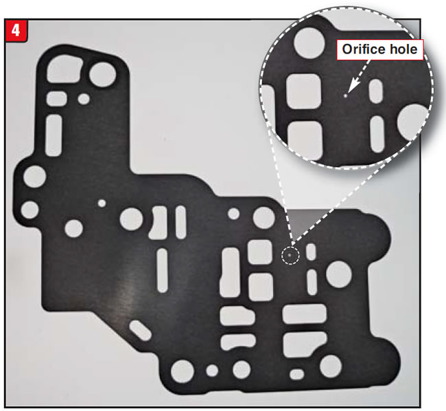
The separator plate for the auxiliary body has an orifice hole for the reverse apply passage (Figure 4). As illustrated, itʼs a rather small hole. It would not take much to block it.
The valve-body gaskets are what require attention. One difference between Mazda and Ford applications is these gaskets. Kit manufacturers normally sub-pack the two versions separately, one marked Mazda and the other marked Ford. There is not much difference between them (Figure 5). Rule number one: Donʼt assume!
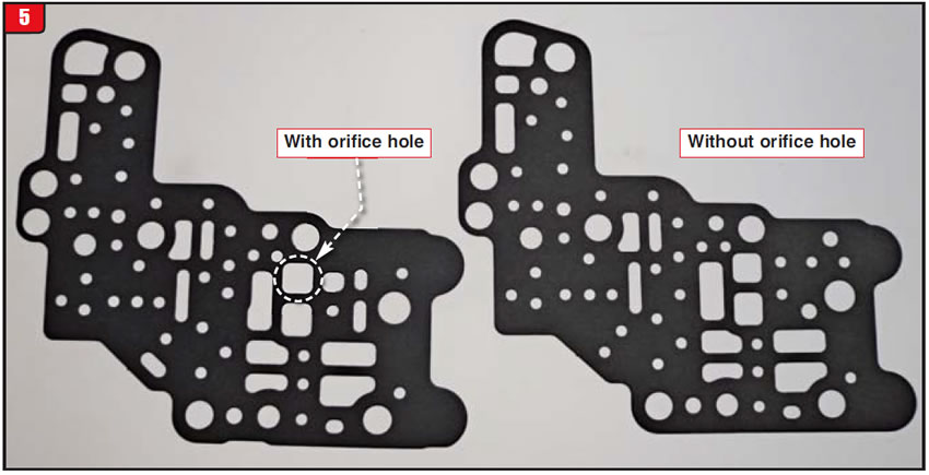
The Ford Fusion in question actually required the Mazda-type gaskets, instead of the Ford-type, and nothing was done to the transmission previously. It is not the first time that this has happened. Figure 5 shows the hole of the gasket corresponding to the orifice hole in the separator plate. Regardless of packaging or part numbers, rebuilding 101 dictates, look closely at the gaskets.


A customer with a 2006 Dodge Durango complains of inconsistent park-to-drive or park-to-reverse garage shifts (morning sickness) shortly after having a transmission service. In conjunction with the application problem are a check engine light and diagnostic trouble code P0868. The vehicle has 82,000 miles on it and did not have any issues prior to the service.
The vehicle was taken for a road test to determine whether upshifts and downshifts were acceptable. The upshifts and downshifts were OK along with TCC lockup. In addition, a scan tool and pressure gauge were used to look for anything abnormal. Nothing was out of the ordinary. As a last resort, the pan was removed to look for damage.
Once the pan was removed, it became obvious what the problem was. The sump filter was split apart at the metal/plastic seam. The fluid was in good condition and there was nothing in the pan, due to the recent service. The question then became, what would be the cause of a sump filter splitting?
There have been instances over the years of filter failures, although they are few and far between, because of different issues. Even back in the days of 325 and 3254L, filter issues did exist. Due to a drain-back problem, GM had Filtran add a rubber one-way checkvalve to the 325/3254L filters, which corrected the condition. The problem came about when the engine was shut off. It could kick backward (counter-clockwise), forcing oil pressure back through the filter, which would result in the checkvalve turning inside out. Restart the engine and the checkvalve would flip back to normal. After several incidents like that, the checkvalve came apart and blue rubber went throughout the transmission. Ultimately, the checkvalves were eliminated and a metal checkvalve capsule was added to the case.
Normally, filters are subjected to negative pressure (vacuum) when the engine starts and the pump draws in fluid. When the pump stops, pressure should equalize and thatʼs that. If for some reason positive pressure remains after the pump stops turning, if only for a moment, a filter could pop open, since it is not designed to handle the internal force.
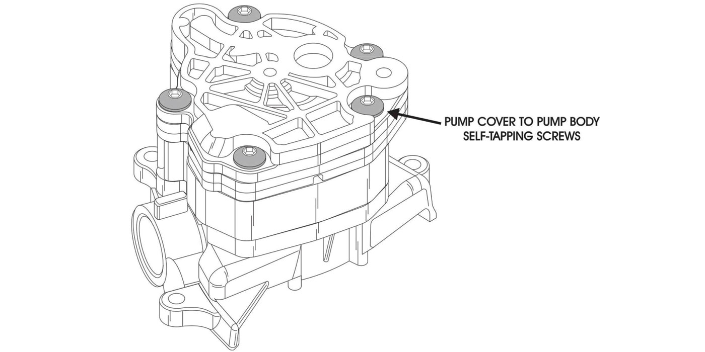
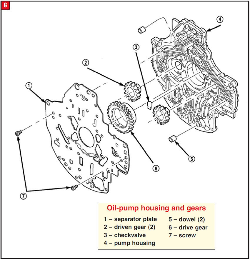
The 45RFE was released in 1999 and has a rather unusual-design pressure system (Figure 6). The pump is a three-gear design: one drive gear and two driven gears. With the engine running at lower speed, both gear chambers generate pressure. As speed increases, the secondary chamber ceases to pump pressure for economy purposes. There is a checkvalve that controls the function.
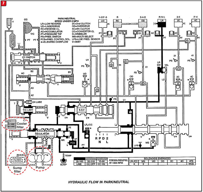
In addition to the normal sump filter that all automatic transmissions have, the 45RFE also uses a cooler-return filter to further protect the hydraulic system from debris. The cooler filter is tied to the sump filter to provide continuous flow (Figure 7). It is the cooler filter that may contribute to the sump-filter blow-out problem even though there are pressure-relief capabilities.
Although the 45RFE was launched in 1999, the filter issue did not arise until later. Chrysler had issued a TSB concerning the problem in 2005 #21-016-05 and updated it in 2006 #21-007-06. A change in the cooler-return filter had occurred and apparently caused this problem. The correct filter part number to use is 4799662. Any filter with an AB suffix is suspect and should not be installed. The question remaining is, would the cooler-return filter be solely responsible for the problem or not?
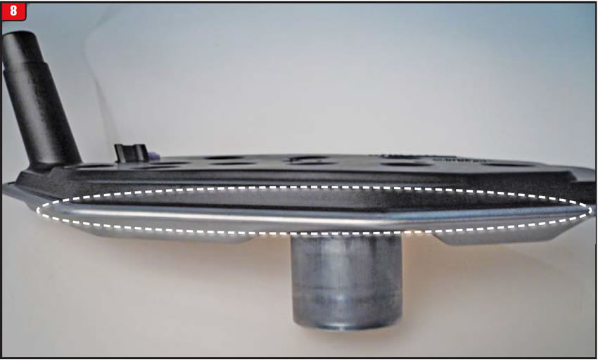
Referring to the oil schematic, it does not appear that the cooler filter would provide enough restriction to split the sump filter; however, anything is possible. If this condition does occur, it would be advisable to install a pressure gauge at the line-pressure-sensor tap as well as the cooler-return-line fitting to ensure that pressure goes to zero the instant the engine stops rotating. Any residual pressure could blow the sump filter (Figure 8). The source of any remaining pressure must be determined and eliminated.
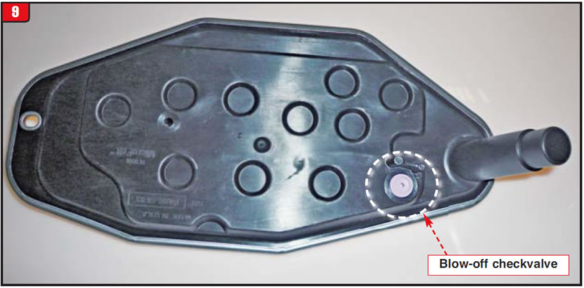
Last, a recent change was made to the sump filter by Filtran to prevent this problem from occurring by adding a blow-off checkvalve to the top side of the filter (Figure 9). By installing the new-design filter, the splitting problem should not occur regardless of the cause.
The next time a vehicle with morning sickness shows up, be sure to drop that pan before removing the transmission.


A customer arrived at the shop with a 2005 Jeep Rubicon. It had a 4.0L engine and an NV241 4WD transfer case. The initial complaint was a hard engagement of the transfer-case shifter. This was due to corrosion of the pivot ball that is part of the shifter assembly. Once the shifter was freed up, the transfer case worked well, going into two-wheel-drive and four-wheel-drive modes.
The vehicle remained at the shop for a day or so in order to have some other repair work done. During a final road check, another transfer-case issue surfaced. The 2WD/4WD indicator light went wacky. At times, either it would not illuminate at all or the light would be reversed, meaning that in 2WD the 4WD position was lit or vice-versa. This issue had nothing to do with the shifter repair.
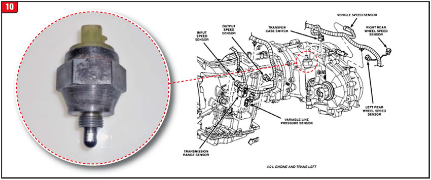
There is a switch on top of the NV241 transfer case that signals various components, including the 2WD/4WD indicator light. It appeared that, coincidentally, the switch decided to take a dump at that exact moment. It is not a normal on-off switch (Figure 10).
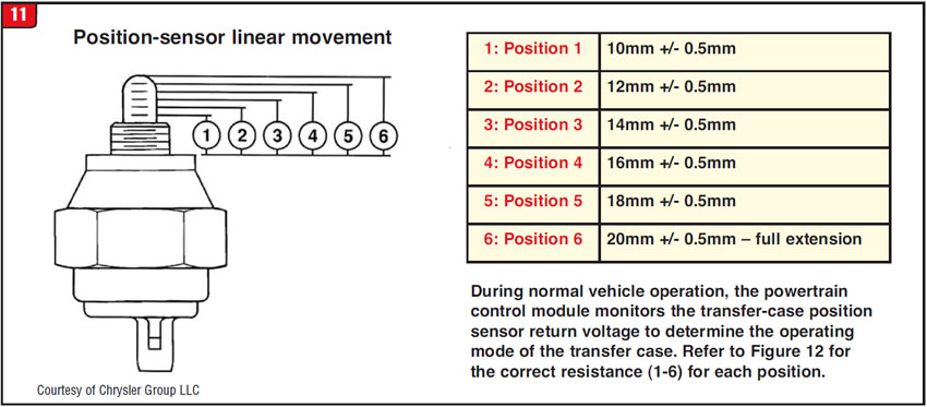
The switch (position sensor) has several steps or stages, which sets it apart from other transfer-case switches. When the shifter cam moves back and forth, it depresses the sensor plunger by a specific amount to provide a given signal (Figure 11). There are six different positions.
Beyond activating the 2WD/4WD indicator lamp, the sensor will also signal other components such as the differential 2WD/4WD controls. Follow all test procedures to ensure that both the front and rear differentials go into two-wheel-drive and four-wheel-drive modes, correctly.
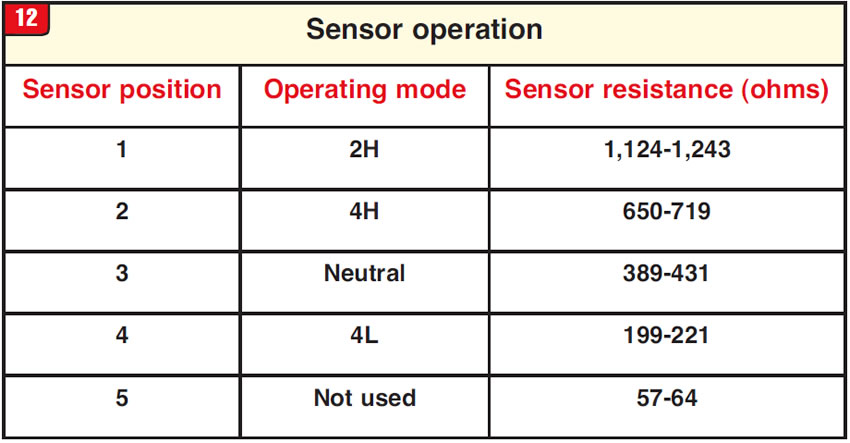
The sensor (part # 5083138AA) can be tested on or off the transfer case by ensuring that the correct amount of resistance (ohms) is achieved at a given sensor-plunger position (Figure 12). Donʼt always depend on the dash light to point the way.

May 2014 Issue
Volume 31, No. 5
- FNR5: inconsistent 5th gear
- 45RFE: engagement issue caused by filter failure
- Jeep Rubicon transfer-case position light