
Up to Standards
- Subject: Operation and diagnosis
- Unit: NVG 244 transfer case
- Vehicle Applications: Dodge Durango, Dakota
- Essential Reading: Rebuilder, Diagnostician
- Author: Mike Weinberg, Rockland Standard Gear, Contributing Editor
I have written two articles for Transmission Digest (September 2006, April 2008) on the mechanical aspects of the NVG 244 electrically shifted transfer case. As time has passed this particular unit has caused a lot of confusion in the field and created a great many tech calls relating to identification of the unit and its operating and electronic diagnosis. In this article we will try to give you more information to give you a better understanding.
Historical evolution of this series of transfer cases starts with the 2000 models. Dodge Durango and Dakota for 2000 had available the 231HD, 241LD and 242, depending on the vehicle’s specific engine and transmission. In 2001, these vehicles were equipped with a 233 or 244. These are electrically shifted units, with the 233 being an electronic 231 and the 244 being an electronic 242.
If the variety of units is amazing, it gets better in 2002 with the availability of the 133 (single-speed unit), 233, 242 and 244. It changes again in 2003, where you find vehicles with the 134, 233 and 244. 2004 saw a design change in the 244, and the 244 Gen II was born. Basically it is the same unit with a heavier-duty case, with 17 10mm bolts attaching the case halves.
From 2004 through 2008, only two units were offered in these trucks, the 144 and 244, which also were found in the Dodge Aspen starting in 2007. For 2009 there are the 140 and the 244 Gen II. As the man says, “You ain’t seen nothing yet.” The 244 and 244 Gen II units are basically a 242 full-time/part-time unit that is shifted electronically.
Now the plot thickens, as there are two designs of the 244. Transfer-case code DHU is an electric shift-on-the-fly part-time unit that has two-wheel drive. Then there is transfer-case code DHV, which has no 2WD, only full-time 4WD and 4 High Lock, Low Lock and neutral. Both designs use a planetary differential to split torque between the front and rear axles in the all-wheel-drive mode. Locking the differential in 4 High or 4 Low creates a 50/50 torque split between front and rear axles and is for off-road use only.
As with the 242, which is the same design but mechanically shifted, tire sizes and pressures are critical for proper operation. The most-common complaint on these units is that shifting out of the four-wheel-drive positions does not release 4wd. This occurs because the differential can get spline locked to the mainshaft if tire pressures are low or differences in tire sizes exceed 1/4 inch in circumference.
The second major issue with these units is dynamic emissions testing on a two-wheel dyno. All four wheels have to be able to turn at equal speeds. If only the rear wheels are allowed to turn on a two-wheel dyno, the differential immediately reaches speeds way above the design limits and self-destructs.
Since we have covered the mechanical aspects in previous articles, we will spend time here going over the electronics of shifting and diagnostic trouble codes. To complete the shifts the 244 has a shift motor and encoder (Figure 1) controlled by a dash-mounted rotary switch. This motor only moves the shift rail to the desired gear, and there is no internal clutch pack, with the planetary-type center differential in the unit splitting torque to the front and rear axles in response to differences in prop-shaft speeds.
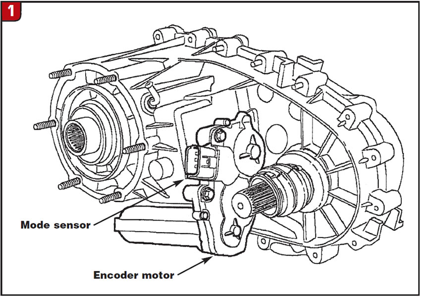
A mode sensor that is part of the encoder motor provides the front control module (FCM) the location of the sector shaft in the transfer case. This sensor is a linear analog position sensor that changes motor-shaft output-shaft position into a DC signal. The FCM supplies a 5-volt signal to this sensor, as long as the FCM is not in sleep mode, to gauge motor position. The motor position is available to the FCM when the ignition is in the run position and for 10 seconds after the ignition is turned off. The mode sensor has a draw of less than 20 milliamps when operational. The FCM monitors the mode-sensor position every two milliseconds whether the shift motor is active or parked in position.
The transfer-case selector switch is on the instrument panel and uses a rotary switch to engage mode and range operations through a resistive network. There is a recessed button for selection of Neutral. To obtain a shift to Neutral, you must use a pen or a key to depress the button so that it cannot be accidentally activated by fingers while you’re turning the knob. As the selector knob is turned, resistance between the mode-sensor voltage-supply pin and the mode-sensor output varies. The FCM then interprets the various resistance positions to create a shift. One important note here is that when you’re replacing a motor, the new motor will be in the all-wheel-drive position, which makes it necessary to manually shift the transfer case into the same position before the new motor will line up.
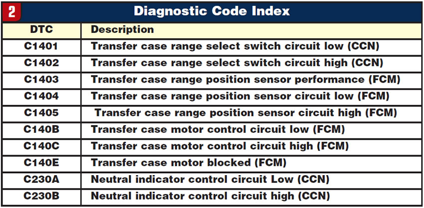
These units are relatively easy to diagnose, as there is no internal clutch pack and there are 10 possible diagnostic codes available (Figure 2).
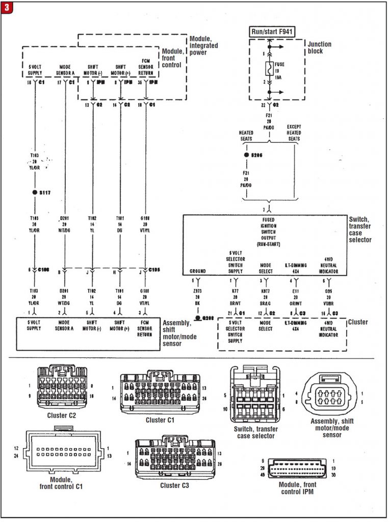
There is not enough room here to supply all the diagnostic trees and wiring diagrams, but I’ve listed the codes and the possible causes with a complete wiring diagram (Figure 3). For further circuit diagrams you will need to obtain the correct schematics from one of the various tech services available. I have found Mitchell OnDemand to be one of the best.
C1401 – Transfer case range switch selector circuit voltage low: voltage lower than 0.1568 volt for 5 seconds
Possible causes:
(K77) 5-volt selector switch supply circuit open
(K77) 5-volt selector switch supply circuit shorted to ground
(K977) mode select circuit shorted to ground
Transfer case selector switch faulty
Instrument cluster failed
C1402 – Transfer case range select switch circuit high voltage: voltage greater than 4.86 volts for 5 seconds
Possible causes:
(K77) 5-volt selector switch supply circuit shorted to voltage
(K977) mode select circuit shorted to voltage
(Z973) transfer case selector switch ground circuit open
Transfer case selector switch faulty
Instrument cluster failed
C1403 – Transfer case range position sensor performance
With ignition on, battery voltage should read 9-16 volts, no range position sensor voltage high or low conditions present
Set condition – During a blocked shift attempt, motor current shows motor movement, but the sensor value change is below the specified value.
Possible causes:
(T103) 5-volt supply circuit high resistance
(T103) 5-volt supply circuit shorted to ground
(T103) 5-volt supply circuit shorted to voltage
(D201) mode sensor signal shorted to voltage
(D201) mode sensor signal shorted to ground
(G180) drivetrain sensor return circuit high resistance
Transfer case motor
Front control module
C1404 – Transfer case range position sensor circuit low (FCM)
Ignition on, battery voltage 9-16 volts
Set condition – Front control module (FCM) detects a short to ground on the transfer case position sensor circuit for 2 seconds.
Possible causes:
(T103) 5-volt supply circuit open
(T103 5-volt supply circuit shorted to ground
(D201) mode sensor “A” circuit shorted to ground
Shift motor/mode-sensor assembly
Front control module
C1405 – Transfer case range position sensor circuit high (FCM)
Ignition on, battery voltage 9-16 volts
Set condition – The FCM detects 5.0 volts on the transfer case range position sensor signal circuit for 2 seconds.
Possible causes:
(T103) 5-volt supply circuit shorted to voltage
(D201) mode sensor “A” shorted to voltage
(D201) mode sensor “A” circuit open
(G180) FCM circuit open
Shift-motor/mode-sensor assembly faulty
FCM failed
C140B – Transfer case motor control circuit low (FCM)
Ignition on, battery voltage 9-16 volts
Set condition – FCM detects low voltage on the transfer case motor control circuit for 0.5 second.
Possible causes:
(T101) shift motor positive circuit open
(T102) shift motor negative circuit open
(T101) shift motor positive circuit shorted to ground
(T102) shift motor negative circuit shorted to ground
(T101) shift motor positive circuit shorted to (T102) shift motor negative circuit
Shift motor-encode sensor assembly faulty
Power-distribution module
Front control module
C140C – Transfer case motor control circuit high (FCM)
Ignition on, battery voltage 9-16 volts.
Set condition – FCM detects high voltage on the transfer case motor control circuit for 2 seconds.
Possible causes:
(T101) shift Motor Positive circuit shorted to Voltage
(T102) shift motor negative circuit shorted to voltage
(T101) shift motor positive circuit open
(T102) shift motor negative circuit open
(T101) shift motor positive circuit shorted to (T102) shift motor negative circuit
Shift-motor/mode-sensor assembly faulty
Integrated power module
Front control module
C140E – Transfer case motor blocked (FCM)
With ignition on, no system voltage condition over or under specification.
Set condition – The FCM is unable to engage the selected range.
Possible cause:
Transfer case internal damage
Transfer case motor faulty
Front control module failed
C230A – Neutral indicator control circuit Low (CCN)
With ignition on
Set condition – Instrument cluster detects low voltage on the neutral indicator control circuit.
Possible causes:
(G95) 4WD neutral indicator circuit open
(G95) 4WD neutral Indicator circuit shorted to Ground
(F21) fused ignition output (run/start) circuit open
Transfer case selector switch faulty
Instrument cluster faulty
C230B – Neutral indicator control circuit high (CCN)
Ignition on
Set condition – The instrument cluster detects high voltage on the neutral indicator control circuit.
Possible causes:
(G95) 4WD neutral Indicator circuit open
(G95) 4WD neutral indicator circuit shorted to voltage
Transfer case selector switch faulty
Instrument cluster faulty