

When the Ford 6F50 and the GM 6T70 transmission models were codeveloped, a lot of similarities existed between the two. Such was not the case when the Ford 6F35 and GM 6T40 development was in the works. Although the basic appearance between the 6F35 and 6T40 is in sync, actual interchanging of components is almost nonexistent.
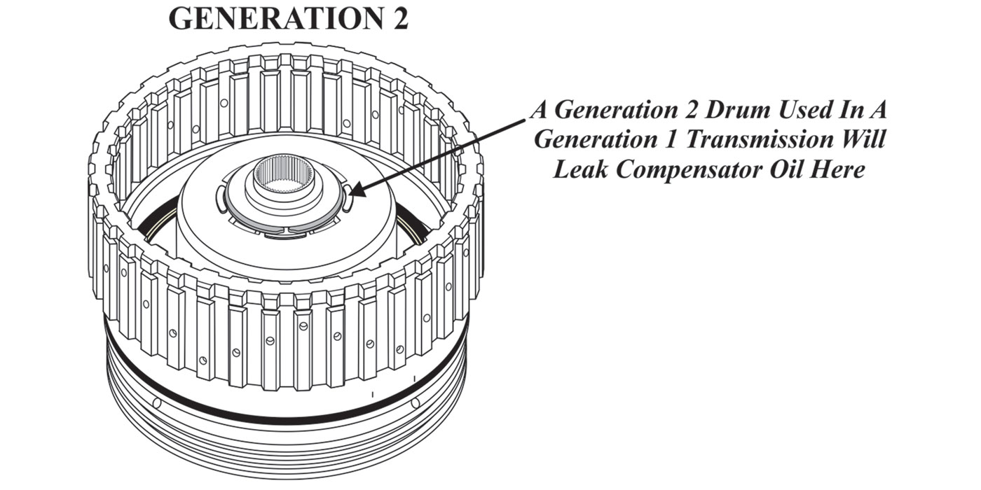
As with the 6F50 and 6T70 models, upgrades that have occurred in the past few years were designated by GEN 1 and GEN 2 for the 6T40 but only by a month and year break with the 6F35. Although changes to the 6F35 started early on, just like GM, things really started to roll by early to middle 2012.
As with other transmission types, changes to the 6F35 have occurred due to premature component failure or to enhance drivability. It is imperative to know about design changes and quality upgrades prior to performing repairs on the 6F35, to avoid receiving incorrect parts or not upgrading to a better design component. Beyond year, make and model information, it is also important to know the physical differences between the transmissions. Externally, there are a few distinctions between models to help with identification, even before the transmission is disassembled.
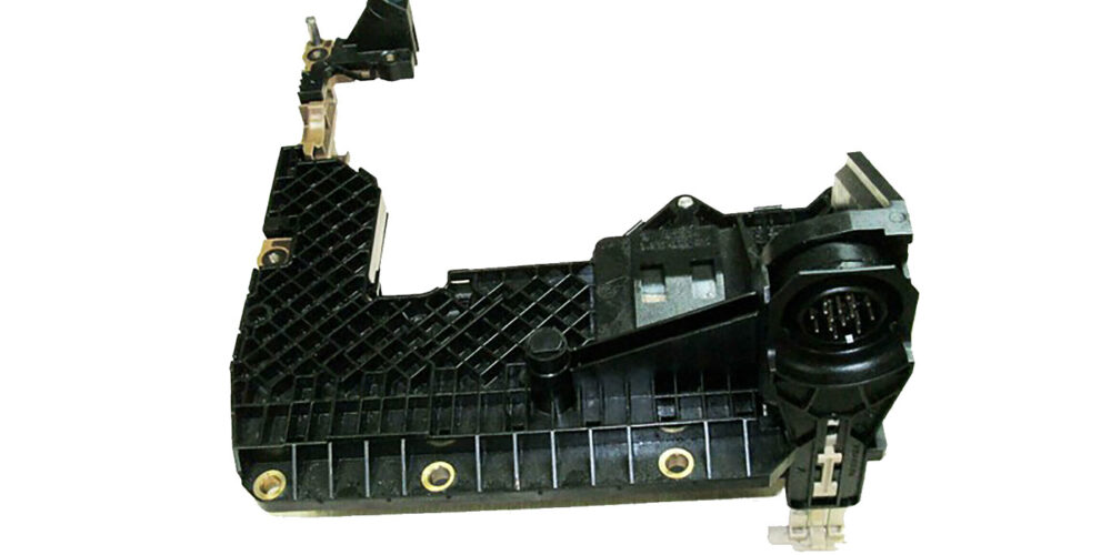
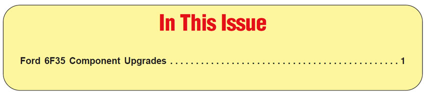
Valve body cover:
Unlike GM that uses a plastic valve body cover on the 6T40, the 6F35 was launched with a metal side cover that has a wide flange for the gasket. The gasket used is a reusable metal type with a rubber bead (Figure 1). Included in the OE package are the gasket, oval solenoid connector seal and a metal support plate. The OE package part number is 9L8Z-7F396-A. The bolt pattern of the cover is nothing like the GM model, however.
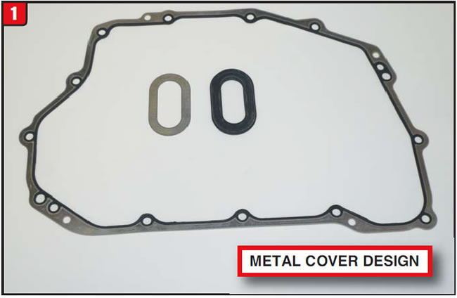
It can be said that great minds work alike due to the fact that by April 2012 Ford decided to bite the bullet and follow GM’s lead by changing over to a plastic valve body cover. Not only was the cover changed to plastic, the gasket design was changed as well. The new design seal component is a rubber spaghetti type, similar to the 6T40, although the two will not interchange (Figure 2). The OE part number for the new design seal is CV6Z-7F396-A. 3 It remains to be seen which one will function the best.
Pump seal:
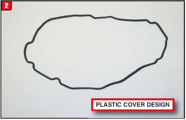
Apparently, there was a concern by Ford relating to a seal pop-out issue of the pump metal clad seal, because a design change was made to the pump and seal by the beginning of 2012. Previous-design pumps had a flanged metal clad seal that pressed flush into the seal pocket of the pump. The newdesign pump seal has a reduced flange diameter as well as a different seal-body diameter and width (Figure 3). The pocket of the pump body was also modified to accommodate this new-design seal, which is now held in place by a snap ring. There is no chance that this seal will pop out.
Bell housing axle seal:
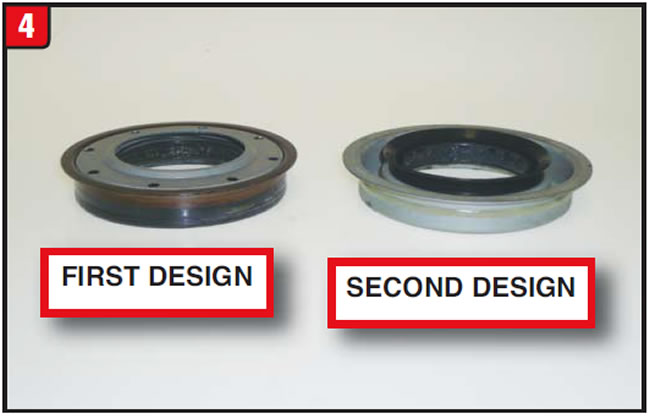
Speaking of metal clad seals, around the same time that the pump seal was being changed, a change was also occurring to the axle seal for the bell housing on 2WD vehicles. Previous-model axle seals had a stone guard on the outside surface (Figure 4). The new-design axle seal does not use a stone guard but has an extended dust lip and a bead of silicone around the OD. The OE part number of the previous design seal is 9L8Z-1177-BA, and the new design seal part number is BB5Z-1S177-C. The design change could only be due to a supplier issue.
Axle bushing:
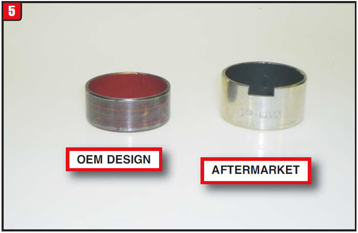
Early on, Ford had an issue with axle seal leaks due to the axle bushing wearing out prematurely. Bushing material has changed a couple of times in order to eliminate the problem. Currently, the OE bushing has a red Teflon coating to enhance durability (Figure 5). A modification that the OEM did not make had to do with dimensions, something that was addressed in the aftermarket. The good folks at Superior Products released a replacement bushing that is noticeably wider than the OE version as well as a toolkit to aid in removal and replacement of the bushing. The toolkit part number is K0100. The updated OEM bushing part number is DV6Z-7025-C. “So much for external items.”
Filter:
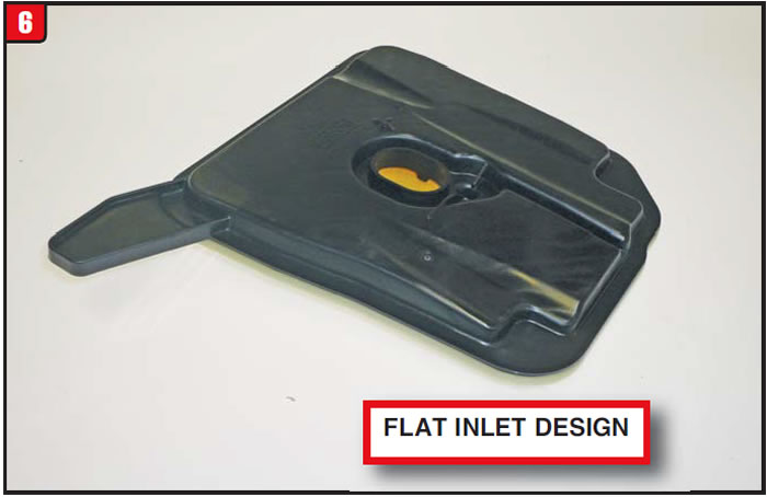
Not only is the transmission filter internal, to get at it requires splitting the bell housing and case, because there is no bottom pan. The 6F35 filter has somewhat of a unique outlet design with how it connects to the pump assembly. It locks into place just like the 6T40 and will certainly not fall out. The first design filters were rectangular however, when Ford decided to make a significant change in the filter design, the rectangular style was replaced by a two-tone square design (Figure 6). The oval inlet is basically flush with the surface of the filter and the filter body has a dogleg.
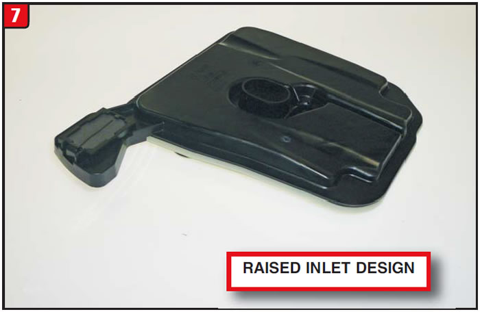
As with other components, by the beginning of 2012, the newest filter (3rd design) was released and was also a two-tone square style, similar to the first design replacement. There are, of course, certain differences between the two-tone designs. One difference has to do with the configuration of the dogleg (Figure 7). In addition, a magnet is incorporated into the dogleg. For some reason, the oval inlet is extended approximately ¼” above the surface of the filter. The filter OE numbers are 9L8Z-7A098-D (first design replacement) and BB5Z-7A098-D third design.
Valve body assembly:
Another component that created issues early on was the valve body, due to premature wear of the solenoid regulator valve bore. Unlike other scenarios of valve-body wear, in which case the manufacturer would sell a complete valve-body assembly, Ford chose to make the main section of the valve body available separately and at a reduced cost. The part number for the upgraded design is CV6Z-7A100-B and although new, does have a core charge.
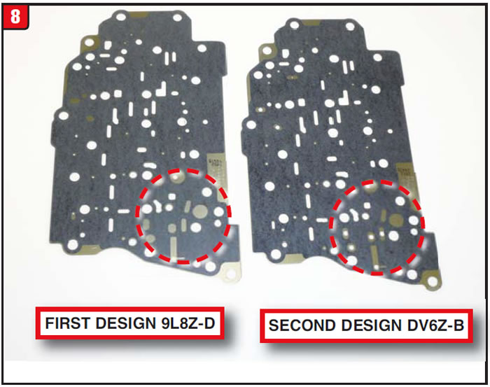
When the new valve-body section was released, it required a new separator plate that goes between the main body and solenoid body. The separator plate has been modified several times resulting in two separator plates to service all models (Figure 8). The part number of the first design separator plate that goes with first design valve body (cast # 9L8P) is 9L8Z-7Z490-D. The new-design valve body (cast # CV6P) requires a separator plate, part number DV6Z-7Z490-B.
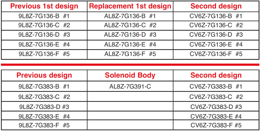
The solenoid body also got a facelift, which created not only more interchange issues but also a noticeable change in cost to repair. The first-design solenoid body part number is AL8Z-7G391-C and cost a ton. The new-design solenoid body, which was released in 2012, is part number CV6Z-7G391-A and is less than half the cost of the previous version.
Solenoids:
Manufacturers cannot leave well enough alone, even when it comes to solenoids, as is the case with the 6F35. There are three basic solenoid types used, variable low bleed, variable high bleed and an on-off shift solenoid. Upgrades affected solenoid design availability differently as well as cost to replace. The problem is not with the low-variable bleed or shift solenoids but with the high-variable bleed type. Both the first-design low- and high-bleed solenoids have a metal barrel where the O-rings are, whereas the second-design solenoids have a plastic barrel. All four types (early/late, low/high bleed) have different barrel dimensions.
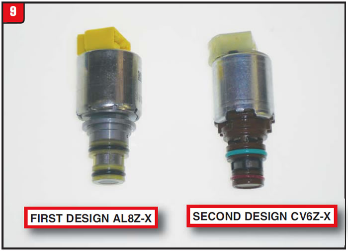
Upgrades started to phase in beginning in 2011. The variable low-bleed solenoid group number is 7G136 and there are five different options based upon stamp number. When the second-design version was released, the plastic barrel was colored brown for identification (Figure 9). The large diameter of the first design solenoid metal barrel is 0.747 and the new design dimension is 0.737. The small diameter of the solenoid barrels is also different. When replacing any solenoid, use the same stamp number from the original. See the part/stamp numbers in the first table below.
The big wrinkle has to do with the variable high-bleed solenoids for the first design applications. Unlike the low-bleed solenoids, which are available separately for the upgraded first design and the new second design, Ford chose to not offer a first-design high-bleed solenoid separately. The only way to obtain the early-design high-bleed solenoids is in the super-expensive solenoid body, part number AL8Z-7G391-C.
When the new-design variable high-bleed solenoids were released, the plastic barrel of the solenoid was colored black for identification (Figure 10). As with the low-bleed solenoids, the high-bleed versions also have different barrel dimensions that fit into the solenoid body bores. The first-design metal barrel large diameter is 0.767 and the plastic second-design dimension is 0.762. The small dimension of the two barrels is also different. See the part/stamp numbers in the second table below.

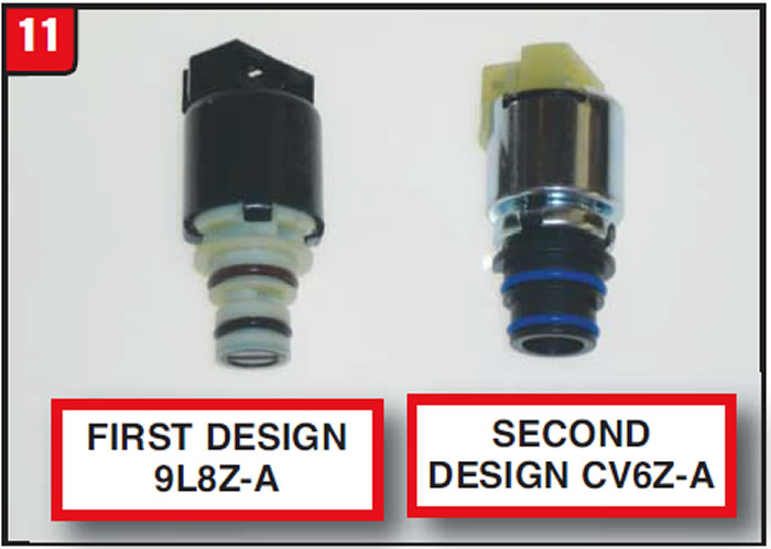
Lastly is the shift solenoid, which was also upgraded to a new design. Unlike the variable-bleed solenoids, the first- and second-design shift solenoids are noticeably different (Figure 11). The barrel of the new design solenoid is noticeably larger than the previous version. Both types are available separately under part numbers 9L8Z-7G484-A (first design) and CV6Z-7G484-A (second design).
Internally additional upgrades were made by early 2012 to several components, least of which the friction material. Certain item upgrades are merely supersessions, while others result in varying design levels. At some point a new designed component may be used to retro back, even though the previous part is still available.
Forward clutch (1-2-3-4):
First-design forward frictions had a full wafer material as most transmissions have. The new-design forward friction is a segmented type, which is what many manufacturers are changing over to (Figure 12). Beyond the friction material is the issue of waviness, which was also tweaked from the previous design plate.
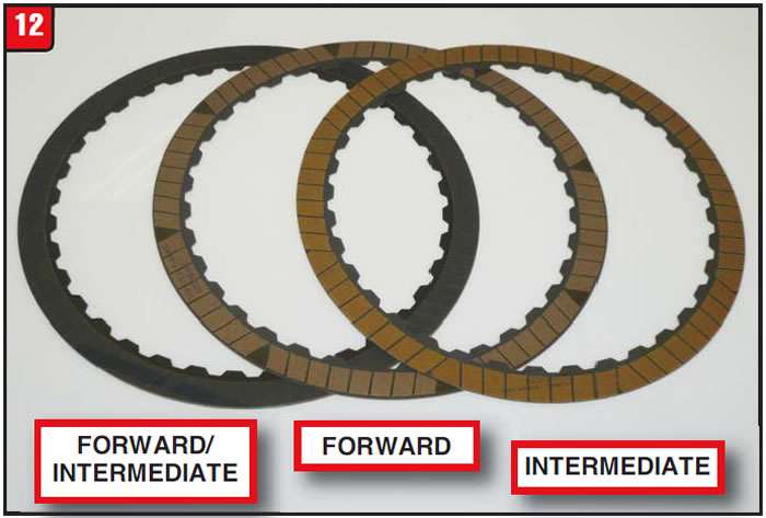
Another change that occurred had to do with position. First design forward frictions were also used for the intermediate clutch pack. Ford chose to change that scenario, so that now there is a different part number to service the forward and intermediate positions. The part number for the second design forward plate is CV6Z-7B164-B and the second design intermediate plate is CV6Z-7B164-C.


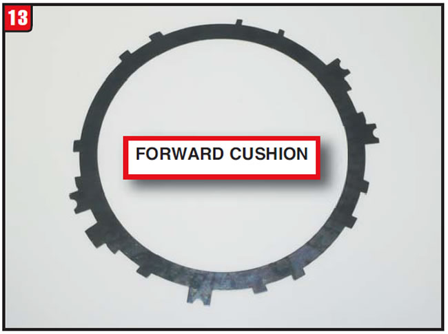
Cushion-spring failure has been a big issue with the Ford and GM FWD six-speed transmissions. Sometimes the springs may be modified and require a first and second design while others are merely an improvement. The 6F35 forward cushion spring was improved and one fits all (Figure 13). The OE part number for the new design is 9L8Z-7B070-F.
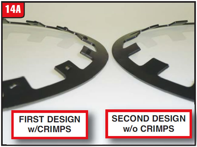
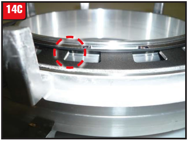
Another problem involving the forward clutch had to do with the piston return spring and snap ring popping out of the center support. To eliminate the problem, Ford redesigned the piston return spring and actually removed the snap ring retaining crimps (Figure 14A).
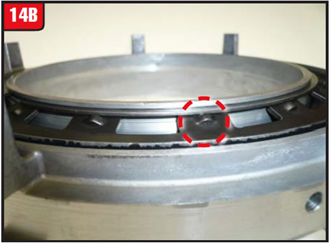
Dimensionally, the first and second design return springs were almost identical. The big change had to do with an additional component. Previous design piston-return snap rings were held into the center support by the crimps on the spring (Figure 14B).
The new design set up uses a cupped retainer between the snap ring and return spring in order to keep the snap ring from popping out (Figure 14C). The first-design return spring OEM part number is 9L8Z-7B070-G and the second-design number is DG9Z-7B070-B. A loaded upgraded center support is available under part number DG9Z7A130B and is inexpensive to boot.
Low/reverse clutch:
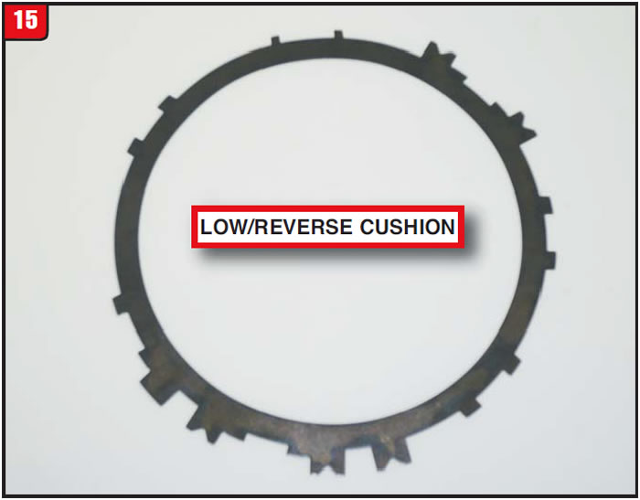
Just like the forward clutch, the cushion spring for the L/R clutch was modified to improve durability and shift feel. The L/R cushion plate is similar to the forward clutch cushion except for a larger ID (Figure 15). It is advisable to mark both the forward and L/R cushion springs during disassembly to make it easier to reassemble the unit. The OE part number is 9L8Z-7E085-C.
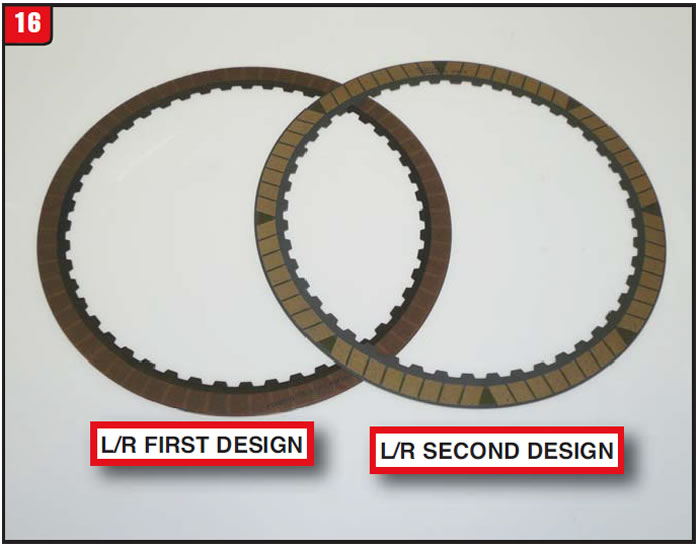
Even though low/reverse is a static brake, Ford changed the friction material as was done to the forward and intermediate clutch plates by changing to the button (segmented) friction design (Figure 16). The waviness of the plate was also affected somewhat along with the grooving pattern in order to reduce drag during clutch release. The part number for the previous design friction plate is 9L8Z-7B164-A and the new button design is part number BB5Z-7B164-C.
Intermediate clutch (2-6):
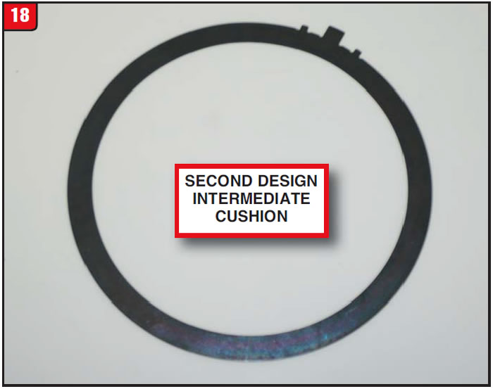
Aside from the change of the friction plate, switching from a full wafer to the segmented friction design, Ford decided to also tinker with the intermediate cushion spring to further enhance clutch apply. The first design cushion spring was perfectly round without any identifying marks (Figure 17).
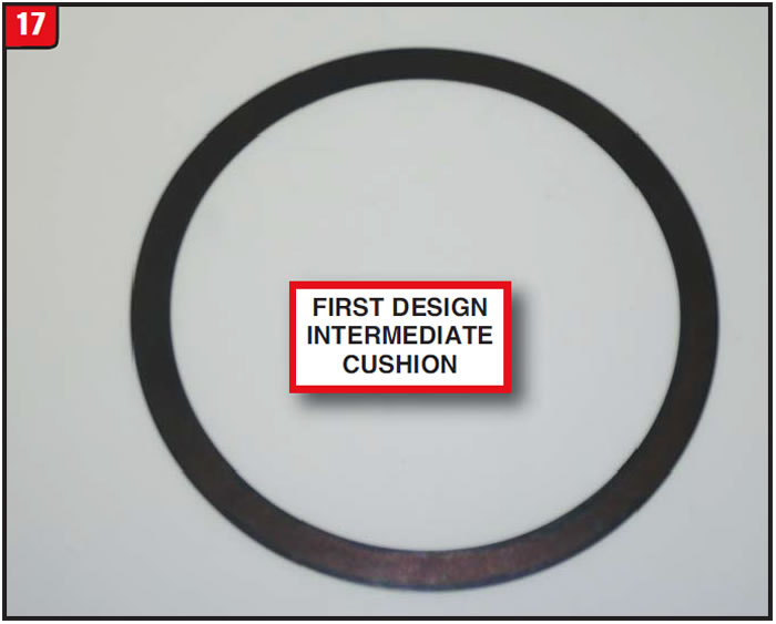
When the second design cushion spring was designed, a couple of tabs were added to the OD of the plate for identification purposes (Figure 18). The new cushion spring is thinner than the previous design as well as having a different wave configuration. The OEM number for the first-design cushion spring is 9L8Z-7E085-A. The second-design cushion spring number is CV6Z-7E085-A.
Rotating clutch direct/intermediate (3-5/R, 4-5-6):
As with the other Ford and GM FWD six speeds, the 6F35 direct clutch has been one of the most sensitive components in the transmission. Unlike GM however, the direct clutch housing has remained unchanged (Figure 19A). Even some of the housing components have escaped the supersession knife.
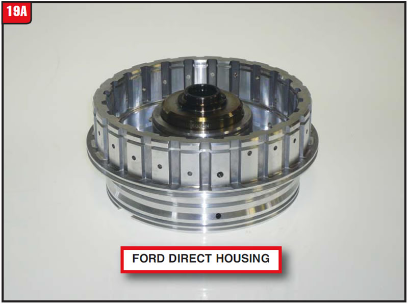
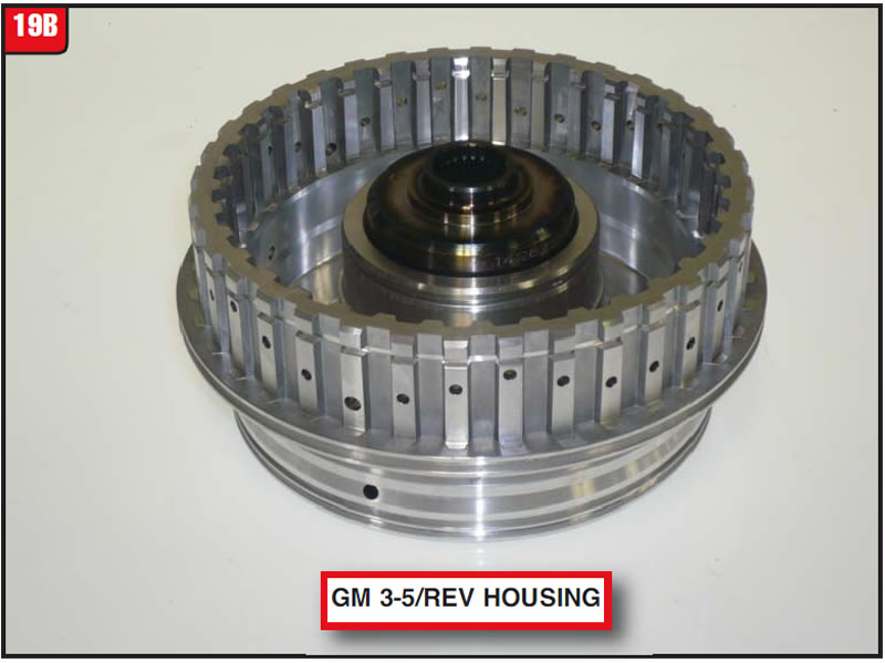
Although most components do not interchange between the 6F35 and 6T40, it escapes logic as to why there is a difference between the Ford and GM direct housings in regard to the clutch splines used. The Ford housing has wide splines, whereas GM uses narrow (Figure 19B). One thing that is common between the Ford and GM housings is that it’s a pain in the rear to remove the input shaft snap ring. The housing part number is 9L8Z-7G384-A.
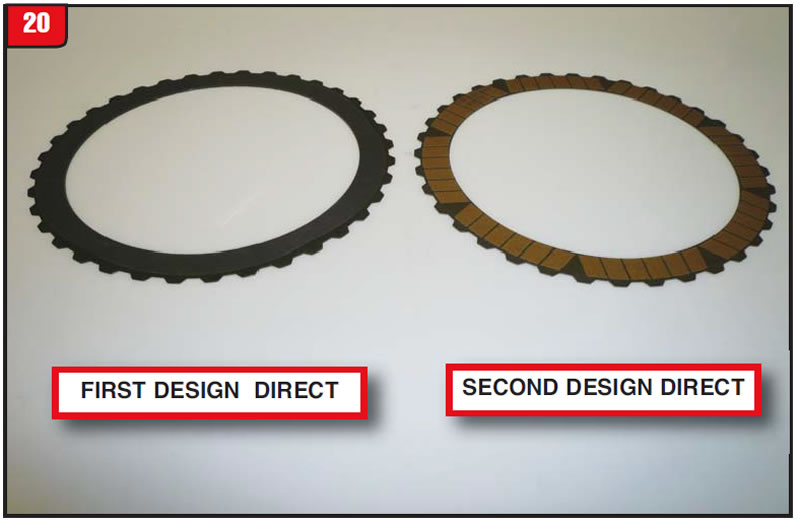
One thing Ford did decide to change was the direct friction, apparently to be in sync with the other friction plates. The new design friction has the same unique grooving pattern as the other segmented frictions have (Figure 20). It remains to be seen if overall performance will be any better than previous models. The previous-design friction number is 9L8Z-7B164-C and the new-segmented design is part number CV6Z-7B164-D. The most critical component in the 6F35, which is the direct cushion spring, is relatively unchanged under part number 9L8Z-7B070-E.
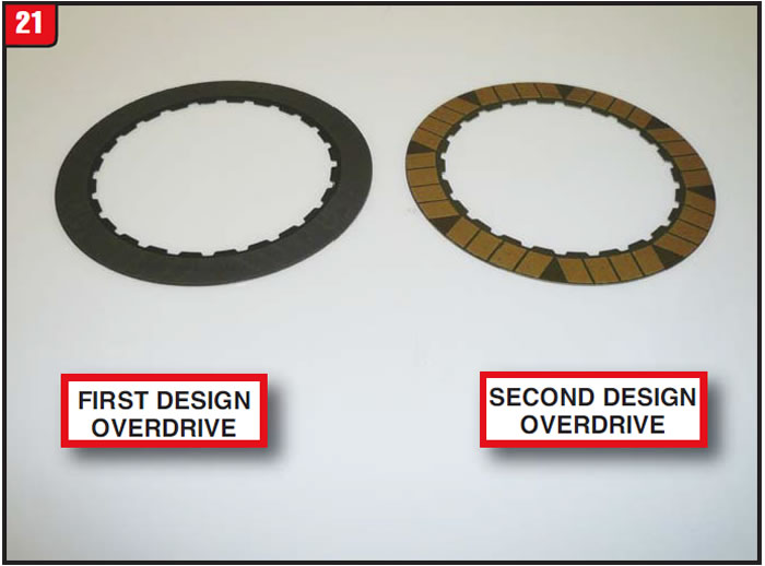
The other item in the rotating clutch assembly that in essence rounds out the line of upgrades is the overdrive clutch friction plate. Ford changed the friction material over to the segmented design, just like the other plates (Figure 21). The new design friction OE part number is CV6Z-7B164-A and the previous friction plate number is 9L8Z-7B164-D. At least there is no cushion spring to deal with.
Case components:
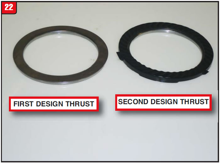
There are other components that have undergone minor changes without affecting adjacent parts. One minor item that was upgraded ultimately affected the case assembly all the way in the back. The thrust bearing, which fits between the direct clutch housing and case, got a noticeable facelift (Figure 22). The plastic that is attached to the new bearing is scalloped on the flat surface, apparently to enhance oil flow as well as having tangs to prevent rotation. There is also a difference in overall thickness that will affect the case pocket. The first-design bearing part number is 9L8Z-7F242-A. The second-design OE part number is BB5Z-7F242-A.
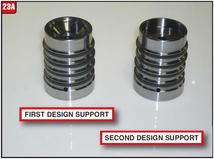
Lastly, another item that was upgraded is also at the back of the bus. The sealing ring support sleeve received a minor tweak, unlike what was done to the GM 6T40, which was changed from four sealing rings to three during the GEN 2 upgrade. There is a cosmetic difference between the first- and second-design 6F35 sleeves (Figure 23A).
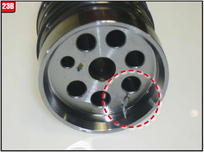
The change to the Ford sleeve has to do with a calibrated leak in the direct clutch circuit. A notch is cut into the bottom of the sleeve to exhaust fluid (Figure 23B). This change goes hand-in-hand with the other calibration changes occurring in 2012. The first-design sleeve part number is 9L8Z-7A130-A and the new-design part number is CV6Z-7A130-B.
Continuous changes or upgrades are always part of the drill with certain items getting a substantial facelift while others are hardly noticeable. Stay tuned for what comes next.


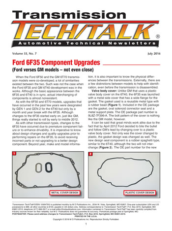
July 2016 Issue
Volume 33, No. 7
- Ford 6F35 Component Upgrades