
TASC Force Tips
- Author: Dan Tucker
With a basic understanding of TAPS, the Transmission Adaptive Pressure System, covered in last month’s article, we will now try to tap into the Steady State Adapt System and what its data can tell us. Not all scan tools provide steady-state data, but I’m convinced that this information is a real help in diagnosing problems in the later GM units. Data for the examples I used in these articles was recorded on either my GM Tech2 or my Mastertech. All the units in the examples shown below are 4T65-Es.
The steady state adapts represent something far different from the 1-2, 2-3 and 3-4 shift-adapt TAPs that we covered in last month’s article. As we noted, the shift-adapt TAPs are pressure adjustments made by the computer during the transition from one gear ratio to another. Notice in Figure 1 the eight different steady-state-pressure lines of data. Each line represents the time after the ratio changes are made. To make it easier, remember that the steady-state TAPs are there to keep the ratio steady. If the computer sees the slightest ratio-calculation error in 1st gear – or maybe I should say, if the computer sees the slightest slip in 1st gear – it instantly raises line pressure in an attempt to stop the slippage by increasing the steady-state TAP 1st-gear adaptive pressure.
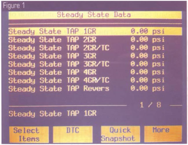
The steady-state adapts represent the rest of the time when the transmission is not changing gears. On an ideal transaxle we would expect to see all the steady-state adapts at 0 psi. This would mean the PCM is not compensating for slip by raising line pressure.
If for some reason the PCM calculates a ratio problem (slip) after the transition from one gear to another is made, the PCM will increase the steady-state-adapt pressure to try to stop the slip. In Figure 2 you see the 3rd-gear TAP at 59.99 psi.
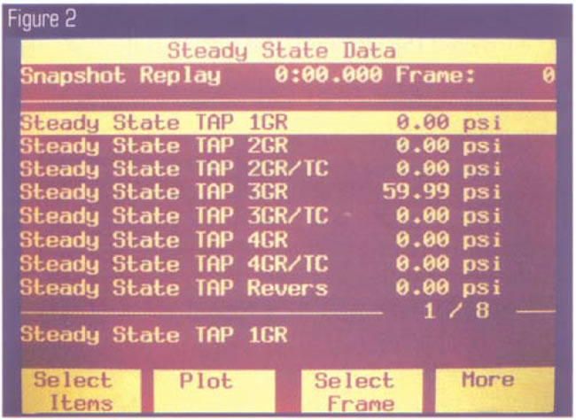
This is an indication that there is slippage in 3rd gear. The only problem is, I never felt it slip while driving this vehicle! The PCM had seen the slippage, increased the line pressure and corrected the slip. If I had not monitored the steady-state adapts I would never have known I had a slip in 3rd.
The customer’s complaint was a harsh 3-4 shift. This was caused by the PCM raising the line pressure in 3rd and making the 3-4 with the line pressure going into the shift at 59.00 psi above normal. Remember that the shift-adapt system has the ability to make small pressure adjustments during the transition of the shift (1-2, 2-3 and 3-4), and because this transaxle was slipping in 3rd after the 2-3 shift, the PCM corrected the slip with the steady state TAP increasing line pressure above what it should be. But, there’s no way the 3-4 TAP can correct it that fast, and the result is a harsh 3-4.
Now, this is completely different from what we are used to seeing when it comes to troubleshooting a harsh shift. The fix for the harsh 3-4 shift was to replace the third-clutch piston, as the rubber was blown off the piston.
In Figure 3 we have a readout of very high steady-state-adapt second-gear pressure. Notice that the pressure is at 249.94 psi. The customer’s complaint was no 2nd. The vehicle shifted from 1st, then remained in 1st when the PCM commanded second, with third and fourth being OK. The steady-state-adapts revealed a slip in second. Because I had no elevated steady-state adapts in third, I had helpful information for troubleshooting this problem.
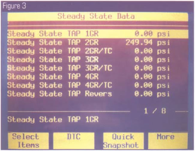
So, here I had the PCM sending extra pressure to the 2nd clutch to try to correct the ratio problem in 2nd, but the transaxle remained in 1st. It could have been a hydraulic leak, but because the 2nd clutch was on in 3rd and 4th, this pointed to the 2nd-clutch plates not holding. Upon teardown of the unit we found that the needle bearing between the 2nd-clutch drum and input drum had failed and the loose needles chewed the lining off the 2nd frictions. So in this case, it was a mechanical failure.
Using the steady-state data is a great diagnostic tool. If you have a customer with a complaint of an intermittent harsh shift or a slip but the problem doesn’t exist at the time, viewing the steady-state data can speed the diagnosis. Any time you see the steady-state-adapt pressure above 0, that is an indication of a slip problem in that gear.
If your initial scan of the steady-state data looks like this:
- Steady State TAP 1GR = 1st gear 229.94 psi
- Steady State TAP Reverse = Reverse 229.94 psi
think twice before you go for a test drive! With readings like this, chances are this vehicle has a restricted filter and you might find yourself walking back to the shop, as I did.
A few other interesting things about the steady-state adapts: For one, there’s no reset function using the scan tool on most vehicles. The 4T80-E is the only computer system I have seen so far with the ability to reset the steady-state adapts. I have flashed the PCM with updated programming and it seems to return the steady states to 0. Most of the time, a long battery disconnect can move the steady-state adapts back to 0. Some technicians don’t believe it is an issue, as the PCM seems to be constantly trying to reduce the steady state pressure to 0 as long as it doesn’t detect a slip. Usually the steady-state adapts go back to 0 after one complete shift cycle on the road. However, be prepared for a harsh shift if the steady-state pressure is high after you have made a repair. It is also common to hear the pump whine, since the steady-state adapts are capable of raising the line pressure by 200 psi or more. My point is, don’t go after pump noise or a harsh shift after an overhaul until you know the steady-state adapts have had a chance to return to normal.
With the transmission industry changing so fast, sometimes it’s easy to overlook small changes. Sometimes these smaller changes turn out to have a big effect on a transmission’s operation. Understanding how some of this often-overlooked and unused scan-tool data works could lead you to a much easier diagnosis the next time you troubleshoot a unit with the GM adaptive-pressure systems. The troubleshooting rules have changed, but so has the technology we have to diagnose the complex vehicles. With all this new information, I believe that even the more-complex transmissions are becoming easier to troubleshoot.

Dan Tucker is the owner of Tucker’s Transmission in Pine Bluff, Ark., and a member of the TASC Force (Technical Automotive Specialties Committee), a group of recognized industry technical specialists, transmission rebuilders and Sonnax Industries Inc. technicians. ©2005 Sonnax


