Torque-Converter Forensics
- Subject: Poor TCC clamping force
- Vehicle Application: Honda
- Essential Reading: Rebuilder, Shop Owner, Center Manager, Diagnostician, R & R
- Author: Ed Lee
Many converter shops have reported having Honda converters returned to their shops because of 740 codes. In most instances, the remedy was to install a new OEM converter.
This confirmed that the code problem was due to an internal converter issue and not any valve-body or other non-converter-related problems. Finding the cause of the 740 codes became a priority, and a root-cause analysis (RCA) began. The first step of the RCA was to collect as many reportedly “failed” units as possible. Many returned units were available, but at first there was no proven method for determining which converters were actually good and which were bad. The traditional method used by most transmission shops is to test the holding power of the clutch (pound-feet of torque) with 40 psi of air over ATF applied to the piston to create the clamping force (Figure 1).
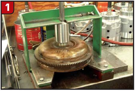
When the “failed” units were tested with this method, they all tested good. A better test method appeared to be in order. An equal number of known-good converters were collected and another series of tests was performed on the combined samples. This time, each unit was tested by applying varying amounts of air pressure/clamping force. The pressure used for the test varied from 10 to 40 psi and was stepped up in 5-psi increments. When the tests were completed, there was a clear division in the range of 20 to 25 psi that separated the good converters from those that had set a 740 code. Converters that previously tested good at 40 psi now were failing in the lower pressure range.
An additional piece of information also was discovered during these tests. Converters with the least amount of clamping force had the largest volume of oil escaping from the exhaust hose on the test fixture. This proved that the poor clamping force was the result of an internal leak. Leaking converters were cut open and inspected.
There are three possible areas for the leaks to occur. One is where the friction material of the torque-converter-clutch (TCC) piston mates to the cover. Since a positive seal is possible in this area, the focus of the inspection moved to the two areas where there is no provision for a positive seal. The other two areas (turbine shaft to turbine hub and turbine hub to TCC piston) rely on the clearance between the mating parts to establish their seal.
The most-likely area for the leak seemed to be between the turbine shaft and the turbine hub, but to be certain, individual flow tests were performed on both areas on all converters. The leak between the input shaft and turbine hub on all converters (both known good and known bad) would flow between 0.2 and 0.5 gallons per minute (gpm). The leak between the turbine hub and the piston, on the other hand, would flow 0.8-4.5 gpm. This leak was obviously a lot more severe.
This test also explains why Honda started using a scarf-cut Teflon seal in this area on its later-model converters. Since the diameters of the turbine hubs on the earlier- and later-model converters were the same, it would be possible to use the later-model seal if a groove could be cut into the hardened surface of the earlier turbine hubs. To cut the groove a special tool was fabricated from a carbide grooving tool. The end of the tool was cut off, rotated 90° and re-welded (Figure 2). The hardened surface turned out to be only a few thousands of an inch deep, and the hub machined easily.
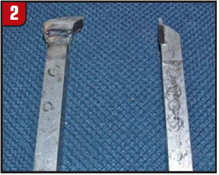
Figure 3 is the turbine hub after the groove is cut, and Figure 4 is the same hub with the late-model seal installed.
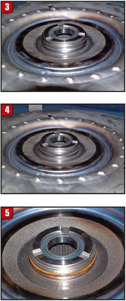
The ultimate test was to put this converter into a vehicle with a 740 code. To date, the converters with the added sealing ring have a 100% success rate. The folks at Consolidated Vehicle Converters (CVC) in Kettering, Ohio, used an O-ring from a General Motors 245mm converter for the seal (Figure 5). CVC’s converter tested best of the lot on the lockup-clutch test fixture (holding more than 150 lb.-ft. of torque at 20 psi).
You may be wondering why 20-25 psi was the sweet spot for testing the Honda converters, rather than the 40 psi that worked on other units. Honda does not use the typical two-path apply-and-release circuit used in the 4R100, 4L60-E, 5R55E and many other applications. Instead, it uses a three-path oil circuit that incorporates a converter bypass valve like the circuits found in some front-wheel-drive Fords; e.g., CD4E, AX4N and AX4S. For this reason the circuit is especially sensitive to outside variables such as restricted coolers and cross leaks. A restriction in the cooler circuit will cause the torque-converter checkvalve to open, which reduces application pressure. If the cooler circuit becomes more restricted, it will react on the valve and may position some valves in a partially stroked position.
Honda converter-charge oil comes from the charge-oil circuit of the main regulator valve. With this design, charge pressure is often only half of what line pressure would be. This is why the lockup clutches of the Honda converters need to be tested at 20-25 psi instead of the 40 psi used on other units.
By adding the groove and seal, converter builders not only are able to rebuild the unit but also are providing their customers a converter that is an improvement over the original early design.

Clearance counts!
Even though the seal cured the test converters, some of the late-model Odyssey converters that already have the OE seal still have lockup problems. The problem with these converters has turned out to be a clearance issue.
In the past, converter technicians who were removing the bearing from the front of the 4R100 turbine hubs to make the clutches apply like those in the E4OD converters learned that 0.080-0.090 inch clearance was necessary between the hub and cover. That same clearance is needed for most of the converters that use the E4OD-style stack-up. The bottom line is that you need sufficient clearance to allow the piston and/or hub to come to a complete stop on lockup application before making contact with the cover.
When GM’s testing proved that the piston was stopped before it contacted the cover on the early 245mm and 298mm converters, engineers reasoned that it was safe to remove the friction-material stops near the inside diameter of those TCC pistons. Some Honda converters have as little as 0.045 inch clearance between the piston and the bearing that rests in the cover. Any machining of the clutch-application surface on the cover or clutch-bonding surface on the piston will make this clearance even less.
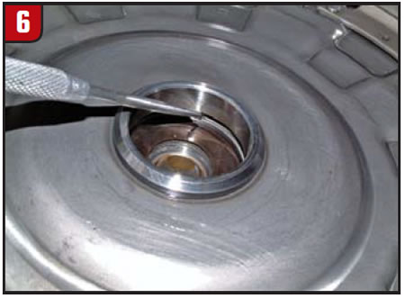
Figure 6 shows the proper clearance between the piston and bearing race. The outer bearing race normally protrudes from the cover about 0.030 inch. If the piston contacts the outer bearing race before coming to a complete stop during lockup application, it will rotate the race in the cover. On occasion the rotation of the race will recess the race down to a point that the top will be flush with the cover. This will affect both the overall height and clutch-release clearance of the converter. To get the piston-to-bearing clearance to the proper tolerance, measure the clearance between the piston and bearing outer race, then machine the front of the piston at the inside diameter. It is usually necessary to remove only about 0.030-0.040 inch.
Ed Lee is a Sonnax Technical Specialist who writes on issues of interest to torque-converter rebuilders. Sonnax supports the Torque Converter Rebuilders Association. Learn more about the group at www.tcraonline.com. ©Sonnax 2010